Dismantling the intermediate shaft
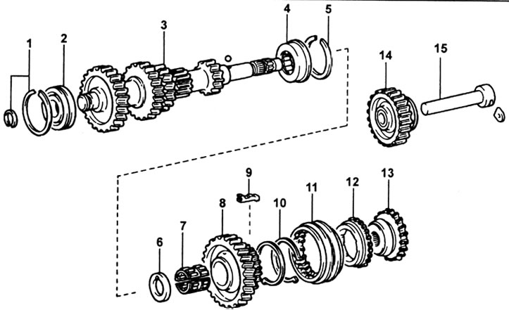
G52 intermediate shaft. 1 - retaining ring, 2 - bearing, 3 - intermediate shaft, 4 - bearing, 5 - retaining ring, 6 - spacer, 7 - needle bearing, 8 - fifth gear, 9 - synchronizer cracker, 10 - synchronizer spring, 11 - synchronizer sleeve No. 3, 12 - synchronizer ring, 13 - synchronizer hub No. 3 (fifth gear), 14 - intermediate gear of reverse gear, 15 - shaft of intermediate gear of reverse gear.
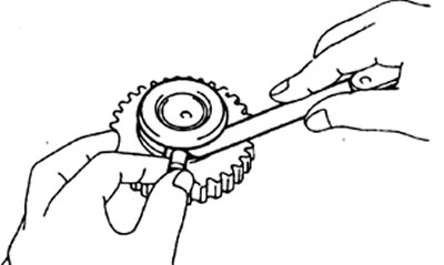
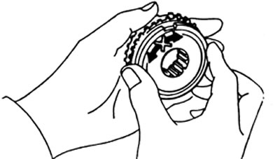
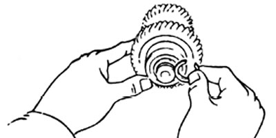
Using a screwdriver, remove the synchronizer sleeve No. 3, three crackers and two springs.
Checking the intermediate shaft
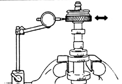
1. Checking the radial clearance of the fifth gear of the intermediate shaft.
A) Install the spacer, needle bearing and 5th gear on the countershaft.
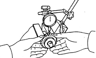
b) Using a digital indicator, measure the radial clearance of the countershaft 5th gear.
Nominal clearance - 0.009 - 0.032 mm
Maximum clearance - 0.032 mm
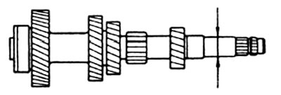
2. Using a micrometer, measure the outer diameter of the shaft journal for the needle bearing.
Nominal diameter - 25.98 - 26.00 mm
Minimum diameter - 25.86 mm
3. Checking the synchronizer ring.
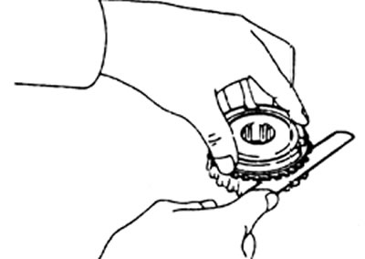
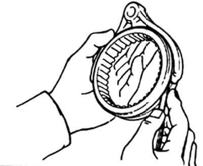
A) By rotating and simultaneously pressing the synchronizer ring, check its frictional properties.
b) Measure the clearance between the ring and the synchronizer hub.
Nominal clearance - 1.0 -2.0 mm
Minimum clearance - 0.8 mm
4. Using a feeler gauge, measure the clearance between the shift fork and the synchronizer sleeve.
Maximum clearance - 1.0 mm
Bearing replacement
If necessary, replace the intermediate shaft front bearing.
A) Remove the snap ring.
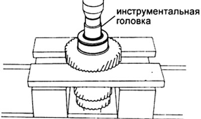
b) Remove the bearing using a press.
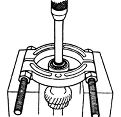
V) Using a press, install the new bearing assembly.
G) Choose a retaining ring of such thickness as to ensure the minimum axial clearance. Install retaining ring.
| Label | Thickness, mm |
| 1 | 2,05-2,10 |
| 2 | 2,10-2,15 |
| 3 | 2,15-2,20 |
| 4 | 2,20 - 2,25 |
| 5 | 2,25 - 2,30 |
| 6 | 2,30-2,35 |
Intermediate Shaft Assembly
1. Install the synchronizer clutch #3 and crackers on the fifth gear.
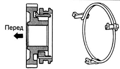
2. Install the synchronizer springs under the crackers.
Attention: it is necessary to install the springs under the crackers in such a way that the end of one spring does not coincide with the end of the other spring, as shown in the figure.
Checking the reverse idler gear
1. Using a digital indicator, measure the clearance of the reverse idle gear.
Nominal clearance - 0.04 - 0.08 mm
Maximum clearance - 0.13 mm
2. Using a feeler gauge, measure the clearance between the reverse gear idler gear and the reverse gear engagement link pin.
Nominal clearance - 0.05 - 0.27 mm
Maximum clearance - 0.5 mm