
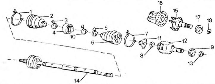
Pic. 179. Installation drawing of the drive shaft. Parts 15 to 18 are only installed on vehicles with flange mounting on the inside. 1. Mounting clamp, large; 2. Rubber cuff; 3. Mounting clamp, small; 4. Vibration damper; 5. Mounting clamp, small; 6. Rubber cuff; 7. Mounting clamp, large; 8 Retaining ring; 9. Boot ring; 10. Dampener clamp; 11. Cross; 12. Internal hinge of torn angular velocities; 13. Retaining ring; 14. Drive shaft with external constant velocity joint; 15. Differential output shaft; 16. Internal constant velocity joint; 17. Boot ring; 18. Retaining ring
When repairing the drive shaft, use the installation drawing:
- Remove the straps from both cuffs. Move the cuff (6) to the middle of the shaft.
- Clamp the shaft in a vice and mark with paint the relative positions of the shaft and the internal joint, as shown in Figure 180. The figure shows a shaft with a drive flange.
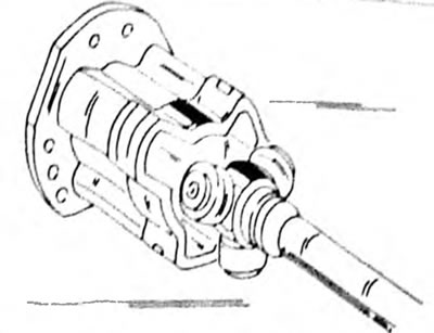
Pic. 180. Before removing the hinge body, apply paint to mark the relative position of the crosspiece and the body.
- Remove the joint from the shaft.
- Remove the retaining ring (8) and to mark the relative position of the parts, hit the end of the shaft and the cross with a core. Knock the cross outwards, but without hitting the rollers (Pic. 181).
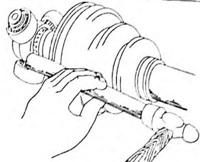
Pic. 181. Use a soft metal drift to knock the cross off the shaft. Apply the drift to the hinge arms
- Remove the cuff from the shaft (2) And (6).
- Using a screwdriver, remove the vibration damper mounting clamp (if installed) and remove the damper from the shaft.
- Clean all parts well. If necessary, replace the broken hinge in the kit. Bent shafts must also be replaced, be sure to replace cuffs that have tears and cracks, as! Dirt may get into the hinges. If the crosspiece is being replaced, do not throw it away temporarily, as it will be needed during assembly.
- Place a large clamp on the shaft (7), cuff (6), small clamp (5), other clamps (10), cuff (2), as well as a large clamp (1) and clamp the shaft in a vice. Wrap the splined part of the shaft with adhesive tape so that it does not damage the cuffs. Be sure to install new clamps. The way the clamps are installed is important because the ends of the clamps must face the direction of rotation of the stool.
- Take the hinge sprocket in your hands and determine on which side there is an internal bevel. This side should face the outer hinge. From the outside, check whether the fasteners match if the previous parts are installed. Place the new hinge so that the hinge roller is in the same position as the old hinge.
- Place the joint on the shaft using a rod (evenly placing the rod in a circle).
- Insert a new circlip into the groove in front of the hinge.
- On the shaft of the series "AT" (1.6 l engine) place 120-130 g of lubricant in the hinge, suppressed together with the repair complex, and lubricate the cuff.
- Lubricate the inner joint and cuff. On the shaft of the series "ST" (2.0 l engine or "ST" (diesel engine) 212-220 g of lubricant required for AT series shaft" (1.6 l engine) — 190 g.
- Align the hinge body with the paint mark on the shaft, as shown in Figure 180, and assemble the parts.
- Place rubber cuffs on the hinges. The protrusion of the cuff should fit into the groove of the shaft.
- Apply clamps and tighten the ends. After this, bend the ends and seal. Secure small clamps with the same convoy. After putting on the cuffs, they should be loose and not too frayed.