Attention: do not open the cover of the control unit unnecessarily (if you touch the terminal of the integrated circuit, it can be damaged by static electricity).
1. Checking the signal from the throttle position sensor.
A) Turn on the ignition. Do not start the engine.
b) Connect a voltmeter to the diagnostic connector "TT" And "E1".
Table. Transmission operating modes in case of normal operation of solenoid valves (solenoids) and failure of one or two of them
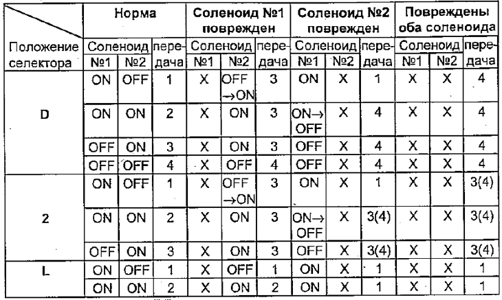
Note: marks "X" indicate a malfunction. () - for A540N.
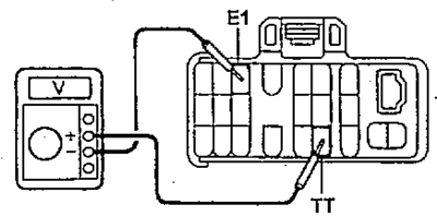
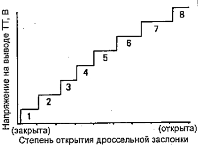
V) While gently depressing the accelerator pedal, check the voltage change. If the voltage does not change as shown in the figure, then the sensor or its circuit is faulty.
2. Check the brake light switch circuit.
A) Press the accelerator pedal all the way down, the voltage at the output "TT" must match the nominal value.
- Rated voltage - 7.6 -8.7 V
b) Press the brake pedal and check the voltage at the output "TT":
Rated voltage:
- brake pedal pressed - no more than 0.5 V
- brake pedal released - 7.6-8.7 V
V) If the measured voltage differs from the specified voltage, then the brake light switch is faulty.
3. Check upshift timing.
A) Warm up the engine to a coolant temperature of 80°C.
b) Set the overdrive switch to "ON".
V) Set the selector to position "D" and the automatic transmission mode switch to the position "NORMAL".
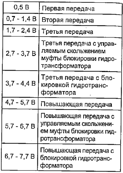
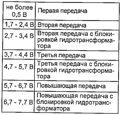
G) During road test (speed over 10 km/h) check the voltage change at the output "TT" connector of the automatic transmission control unit and the engine during upshifts.
d) If the voltage rises from 0 V to 7 V, then everything is normal (see table).
Except A245E since 1996
A245E since 1996