
Cabin air conditioning wiring diagram
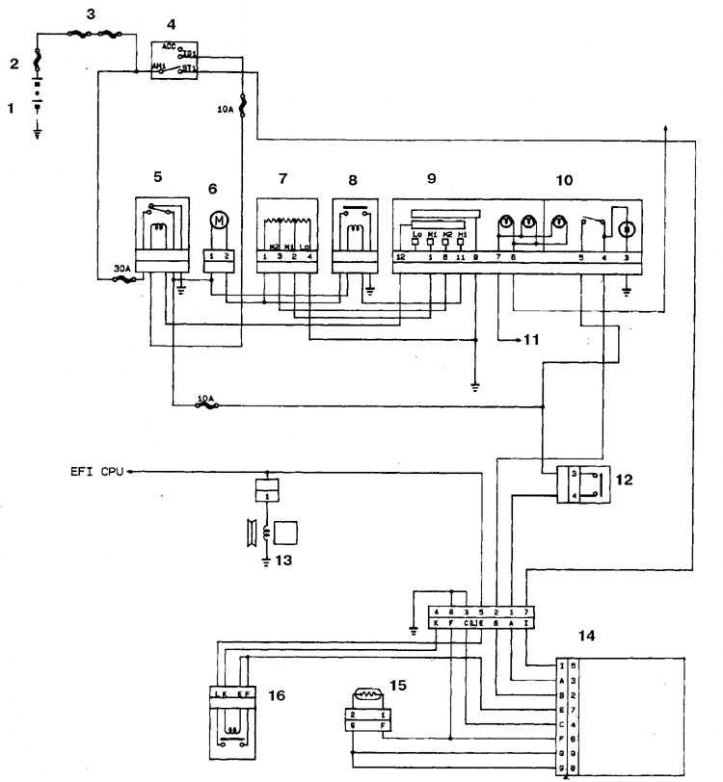
1. Battery; 2. Main fuse; 3. Additional fuse; 4. Ignition switch; 5. Heater relay; 6. Electric motor; 7. Resistor; 8. Motor relay; 9. Fan switch; 10. Air conditioner switch; 11. To the rheostat; 12. Air conditioning pressure sensor; 13. Electromagnetic clutch; 14. Amplifier; 15. Thermistor; 16. Cut-off temperature switch
Location of heater and air conditioner units
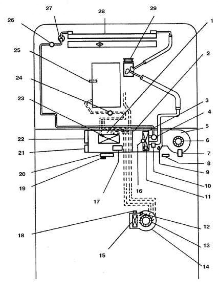
1. Heater; 2. Cooling unit; 3. Evaporator; 4. Expansion valve; 5. Fan; 6, 13. Electric motor; 7. Air damper motor; 8. Amplifier; 9, 12. Fan resistor; 10. Fan speed switching relay; 11. Cut-off temperature relay; 14. Rear heater; 15, 23. Radiator; 16. Thermistor; 17. Mixing damper motor; 18. Rear heater relay; 19. Rear heater switch; 20. Air conditioning control panel; 21. Mixing damper motor amplifier; 22. Ventilation nozzle motor; 24. Crane; 25. Thermal relay; 26. Pressure switch; 27. Moisture separator; 28. Capacitor; 29. Compressor
Heater motor connector and connector wiring
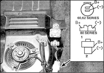
1. 80 series front heater connector
2. 80 series rear heater connector
The heater blower unit is mounted under the front panel, or in the passenger compartment on vehicles with rear air conditioning.
Examination
Attention! When working on the heater of a part of the car, deactivate the airbag. To do this, turn the ignition key to the LOCK position, disconnect the battery from the ground and start work no earlier than after 2 minutes.
1. If the fan fails, check the fuse, the condition of the contacts and wires, and the state of charge of the battery.
2. Check for battery voltage at the motor connector (turn on the ignition and move the fan knob to the ON position).
3. If there is no voltage, then there is a break in the wires from the ignition switch or from the switch.
4. If voltage is present, then connect the connector and connect the mass output to ground by connecting a jumper on the back of the connector.
5. If the fan does not turn on, the motor may be defective.
6. In this case, connect the motor leads directly to the battery and ground with fused wires.
7. If the motor does not turn on, it must be replaced.
8. If the engine is working, then check the resistor or switch, for which remove the heater control panel (see subsection 4.11).
Replacement
1. Disconnect the connector, remove the connector bracket, unscrew the 3 screws and remove the blower unit from the casing.
2. The impeller can be removed and installed on a new electric motor.
3. Installation is carried out in the reverse order.