Types 2.0 kW and 2.2 kW
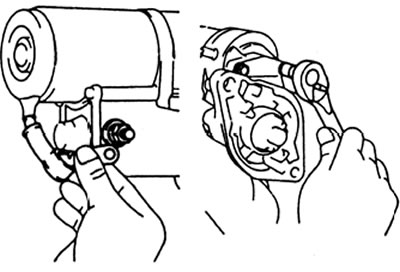
A) Remove the nut and disconnect the lead wire from the magnetic switch terminal.
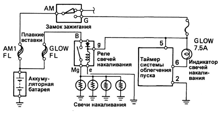
Engine 3L
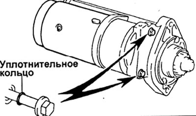
b) Remove the two bolts, spring washers, plate washers and o-rings.
V) Remove the excitation block together with the anchor.
G) Remove the sealing ring.
Types 2.5 kW and 2.7 kW
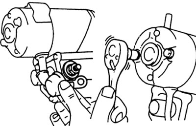
A) Remove the nut and spring washer, disconnect the lead wire from the traction relay terminal.
b) Remove the two through bolts, spring washers, plate washers and o-rings.
V) Remove the excitation block together with the anchor.
G) Remove the felt washer and lock plate.
2. Remove the starter housing, clutch assembly and gears.
Types 2.0 kW and 2.2 kW
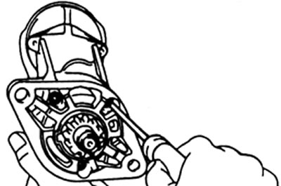
A) Remove two screws.
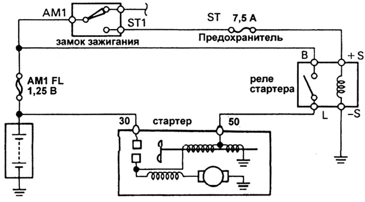
Launch system (engine 1KZ-T)
- For a 2.2 kW starter, remove the two through screws
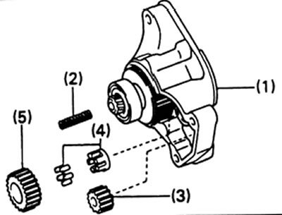
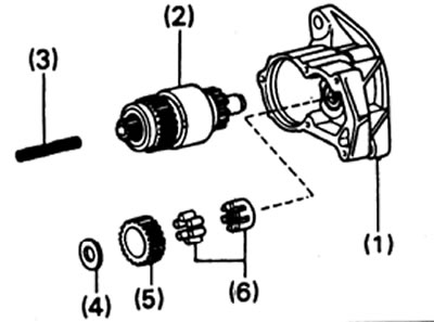
b) Remove from the traction relay:
- (1) starter housing and clutch assembly,
- (2) return spring,
- (3) drive gear,
- (4) overrunning clutch,
- (5) parasitic gear.
Types 2.5 and 2.7 kW
A) Remove three screws.
b) Remove from the traction relay:
- (1) frame,
- (2) clutch assembly,
- (3) return spring,
- (4) plate washer,
- (5) parasitic gear,
- (6) overrunning clutch.
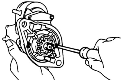
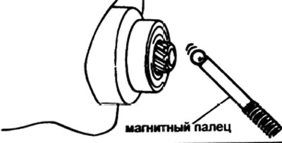
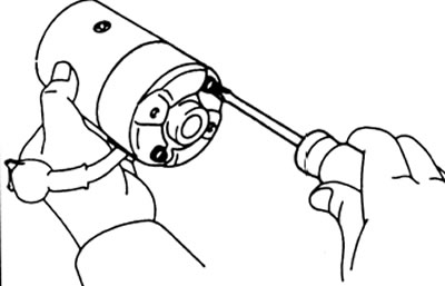
3. (All types) Using a magnetic finger, remove the steel ball from the hole in the clutch shaft
4. Remove the brush holder.
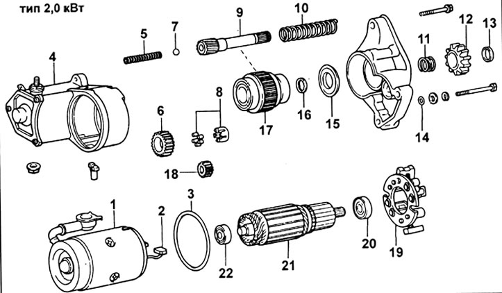
Starter 2.0 kW: 1 - excitation winding, 2 - brush, 3 - sealing ring, 4 - traction relay, 5 - return spring, 6 - parasitic gear, 7 - steel ball, 8 - overrunning clutch, 9 - clutch shaft, 10, 11 - spring, 12 - starter drive gear, 13 - circlip, 14 - o-ring, 15 - bearing retainer, 16 - spring retainer, 17 - starter clutch, 18 - armature drive gear, 19 - brush holder, 20 - rear bearing, 21 - armature, 22 - front bearing.
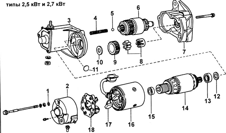
Starter 2.5 and 2.7 kW: 1 - o-ring, 2 - end cap, 3 - traction relay, 4 - return spring, 5 - steel ball, 6 - starter clutch housing, 7 - starter housing, 8 - overrunning clutch, 9 - idle gear, 10 - lamellar washer, 11 - lock washer, 12 - felt seal, 13 - rear bearing, 14 - armature, 15 - front bearing, 16 - excitation coil, 17 - brush, 18 - brush holder.
Types 2.0 kW and 2.2 kW
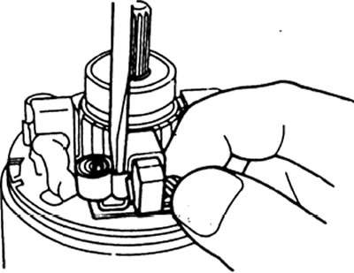
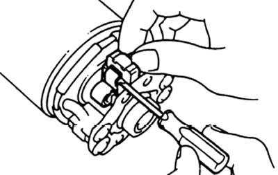
Using a screwdriver, push the spring back and disconnect the brush from the brush holder. Disconnect the four brushes and remove the brush holder.
Type 2.5 kW and 2.7 kW
A) Remove the two screws and end cap from the drive unit.
b) Using a screwdriver, push the spring back and disconnect the brush from the brush holder.
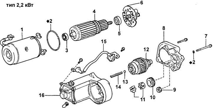
Starter (engine 1KZ-T):1 - excitation winding, 2 - sealing ring, 3 - front bearing, 4 - armature, 5 - rear bearing, 6 - brush holder, 7 - coupling bolt, 8 - starter housing, 9 - drive gear, 10 - "parasitic" gear, 11 - bearing, 12 - clutch assembly, 13 - ball, 14 - return spring, 15 - wire, 16 - traction relay.
Disconnect the four brushes and remove the brush holder.
5. Remove the anchor from the exciter.
Checking the armature winding
1. Check the manifold for an open circuit. Using an ohmmeter, check for continuity between the collector fins.
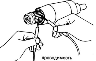
If there is no conductivity, then replace the armature.
2. Check if there is a short circuit in the armature winding "to ground". Using an ohmmeter, check for continuity between the collector and the armature core.
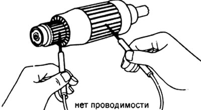
If there is continuity, then replace the armature.
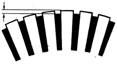
Manifold check
1. Inspect the working surfaces of the collector lamellas, if they are dirty and burnt, clean the working surfaces with sandpaper or grind the collector on a lathe.
2. Mount the anchor on the prisms and measure the runout of the collector. Maximum radial runout: 0.05 mm. If the radial runout exceeds the maximum allowable value, then turn the manifold on a lathe.
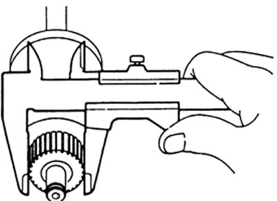
3. Using a caliper, measure the manifold diameter.
Nominal diameter:
- 2.0 kW and 2.2 kW types - 35.0 mm
- 2.5 kW and 2.7 kW types - 36.0 mm
Minimum Diameter:
- type 2.0 kW and 2.2 kW - 34.0 mm
- 2.5 kW and 2.7 kW types - 35.0 mm
4. Check the depth and cleanliness of the slots between the lamellas, the absence of foreign material in them. Standard slot depth: 0.7 - 0.9 mm. Minimum slot depth: 0.2 mm. If the kerf depth is less than the minimum allowable value, correct the kerf with a hacksaw blade.