Reminder: When assembling the starter motor, use a high-melting grease to lubricate the bearings and gears.
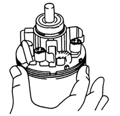
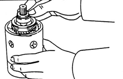
1. Grease the armature bearings, then place the armature in the starter housing.
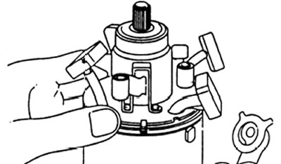
2. Install the brush holder
Types 2.0 kW and 2.2 kW
A) Align the protrusion of the brush holder with the slot in the stator.
b) Position the brush holder on the anchor.
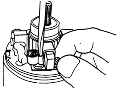
V) Using a screwdriver, hold the brush holder spring retracted and install the brush into the brush holder. Install four brushes.
Reminder: Lay the brush wires so that they do not touch the housing.
Types 2.5 kW and 2.7 kW
A) Position the brush holder on the anchor.
b) Using a screwdriver, hold the brush holder spring retracted and install the brush into the brush holder. Install four brushes.
Reminder: lay the wires of the brushes so that they do not touch the housing.
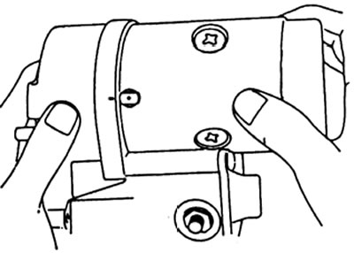
V) Install the end cap with two screws.
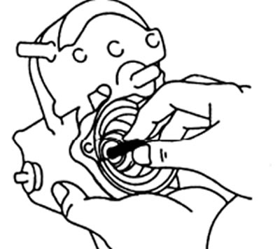
3. (All types) Insert a steel ball into the hole in the clutch shaft.
A) Apply grease to the steel ball.
b) Insert a steel ball into the hole in the clutch shaft.
4. Install the clutch and gear assembly and) Apply grease to the return spring.
b) Insert the return spring into the opening of the traction relay.
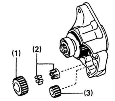
V) (Types 2.0 kW and 2.2 kW) Insert the following items into the starter housing:
- (1) parasitic gear,
- (2) overrunning clutch,
- (3) drive gear.
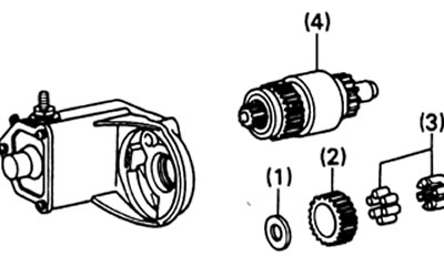
G) (Types 2.5 kW and 2.7 kW) Insert the following items into the starter housing:
- (1) plate washer;
- (2) parasitic gear;
- (3) overrunning clutch;
- (4) clutch assembly.
d) (Types 2.0 kW and 2.2 kW) Assemble the starter housing and solenoid switch with two screws.

e) (Types 2.5 kW and 2.7 kW) Connect the starter housing and the traction relay with three screws.
5. Install the exciter and armature assembly.
Type 2.0 kW
A) Install a new O-ring to the exciter block.
b) Align the mark of the bolting point of the excitation unit with the mark of the traction relay.
V) Install exciter and armature assembly with new o-rings (2 pcs), two plate washers, spring washers and bolts.
Type 2.2 kw
Fasten the wire to the terminal «50» and starter housing
G) Connect the lead wire to the terminal "WITH" and install the nut.
Types 2.5 kW and 2.7 kW
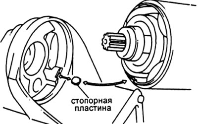
A) Install a new felt seal on the anchor.
b) Install the locking plate into the cutout of the traction relay.
V) Align the lock plate with the exciter block cutout.
G) Install the exciter and valve assembly with two new O-rings, two lamellar washers, spring washers and two through bolts.
d) Connect the lead wire to the terminal "WITH" and install the spring washer and nut.
Checking the characteristics of the starter
Note: each of the tests should be carried out in 3 - 5 seconds to avoid winding failure.
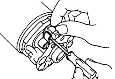
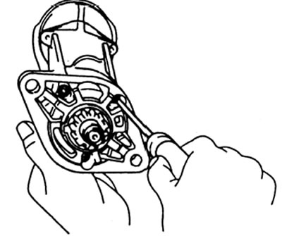
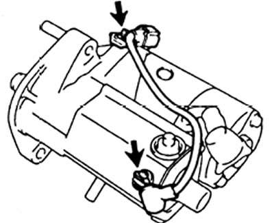
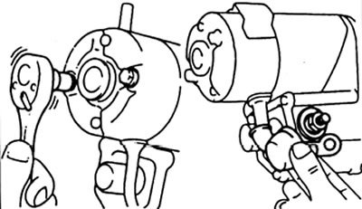
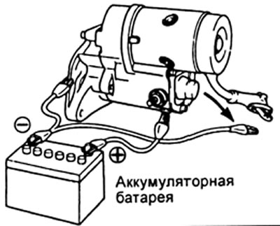
1. Checking the retracting winding of the traction relay.
A) Disconnect the wire from the terminal "WITH" excitation coils.
b) Connect the battery to the traction relay as shown in the figure. Check drive gear outward extension. If the drive gear does not extend, then replace the traction relay.
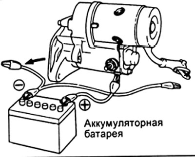
2. Checking the holding winding.
With the connection similar to the previous operation and the overrunning clutch drive gear extended, disconnect the negative (-) terminal wire "WITH". Check that the pinion gear is in the extended position. If the drive gear returns inside, then replace the traction relay.
3. Check if the freewheel drive gear returns.
Disconnect negative (-) wire from the relay housing. Check drive gear return. If the drive gear does not return, then replace the traction relay assembly.
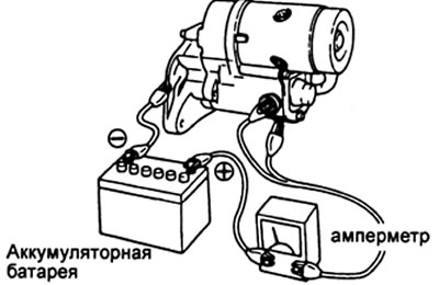
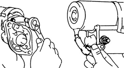
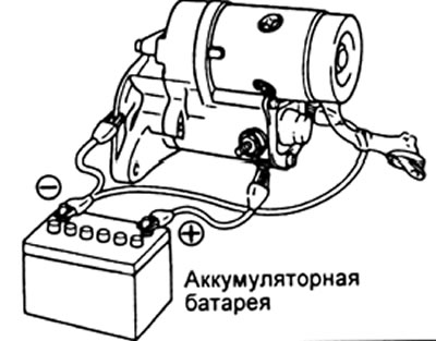
4. Checking the operation of the starter without load.
A) Connect the battery and ammeter to the starter as shown.
b) Check the smoothness of the starter rotation and uniform extension of the drive gear.
Check the ammeter reading.
Rated current:
- 2.0kW and 2.2kW types - 120A max at 11.5V
- 2.5kW and 2.7kW types - 180A max at 11.0V