
To do this, remove the adjusting washer.
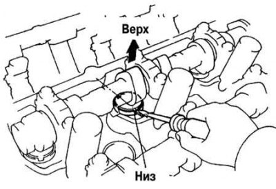
Pic. 2.227. The correct location of the valve lifter
Rotate the camshaft so that the top of the cam is pointing up. Position the valve lifter as shown in Figure 2.227.
Note. Use special tool 09248-05410 (A) and 09248-05420 (IN).
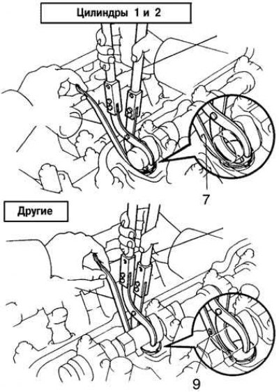
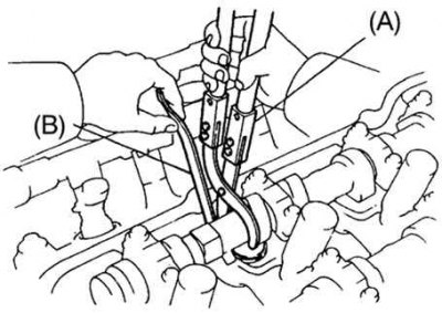
Pic. 2.228. Use of special tools when adjusting thermal clearances in valves
Using a special tool (A), press the pusher and place the special tool (IN) between the camshaft and pushrod. Remove special tool (A). Insert special tool (IN) at a slight angle and make sure that the markings on the special tool are located as shown in Figure 2.228.
If a special tool (IN) inserted too deep, the shim may jam it. To prevent this, insert it from the side of the inlet valves at a slight angle.
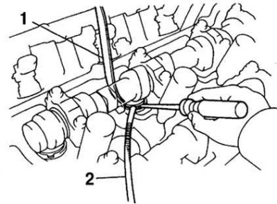
Pic. 2.229. Removing the shim: 1 - special tool (IN); 2 - magnetic rod
Remove the adjusting washer with a small screwdriver and a magnetic bar (pic. 2.229).
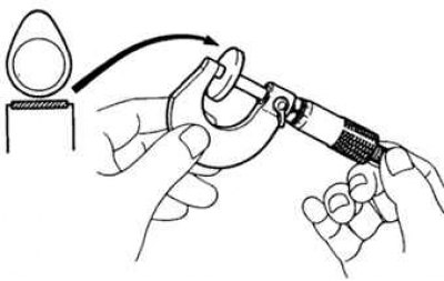
Pic. 2.230. Measuring shim thickness
Using a micrometer, measure the thickness of the removed shim and determine the size of the new shim (pic. 2.230).
Calculate the thickness of the new shim so that the clearance in the valves is within the specified values:
- thickness of the removed adjusting washer - T;
- measured valve clearance - A;
- new shim thickness - N.
11MZ-FE:
- inlet - N = T + (A - 0.2 mm);
- graduation - N \u003d T + (A - 0.3 mm).
Select a new shim with a thickness as close as possible to the calculated value.
Pic. 2.231. Installing the shim
Install the new shim into the pushrod with the stamped number on the shim facing down. Using a special tool (A), press the pusher and remove the special tool (IN) (pic. 2.231).
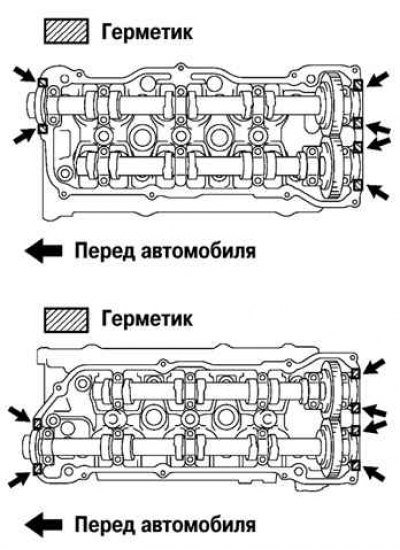
Pic. 2.232. Sealing locations
Check the valve clearance again. Remove the old sealing material and apply sealant to the cylinder head, in the places shown in Figure 2.232.
Install the cylinder head covers.
Install and tighten the spark plugs.
Install the ignition coils.
Install the upper intake manifold assembly.
Install the protective cover.