
Valve clearance check
Remove the cylinder head cover.
Set the No. 1 cylinder piston to TDC on the compression stroke.
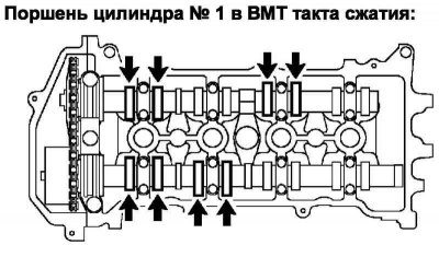
Pic. 2.118. Checked valves
Check up the valves specified in drawing 2.118.
Using a set of flat feeler gauges, measure the clearances between the valve lifters and camshaft lobes.
Valve clearance (cold engine): 0.15-0.25mm for intake valves, 0.25-0.35mm for exhaust valves.
Record valve clearance measurements that do not correspond to the prescribed values. They will be needed later to determine the dimensions of the valve lifters to be replaced.
Rotate the crankshaft 1 turn (360°) and set the No. 4 cylinder piston to TDC on the compression stroke.
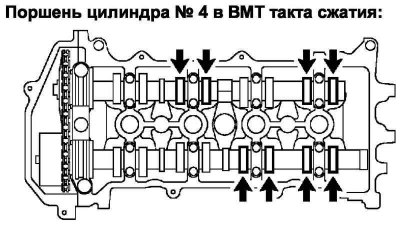
Pic. 2.119. Checked valves
Check up the valves specified in drawing 2.119.
Use a feeler gauge to measure the clearances between the valve lifters and camshaft lobes.
Valve clearance (cold engine): 0.15-0.25mm for intake valves, 0.25-0.35mm for exhaust valves.
Record valve clearance measurements that do not correspond to the prescribed values. They will be needed later to determine the dimensions of the valve lifters to be replaced.
Valve clearance adjustment
Remove camshaft #2.
Remove camshaft.
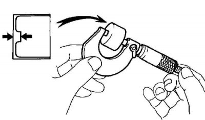
Pic. 2.120. Valve lifter thickness measurement
Using a micrometer, measure the thickness of the removed valve lifters (pic. 2.120)
Calculate the thickness of the new valve lifter so that the clearance in the valve actuator corresponds to the prescribed value.

Valve clearances:
- intake valves A=B+ (C–0.20 mm).
- exhaust valves A=B+ (C–0.30 mm).
Calculation example (intake valves)
Measured intake valve clearance = 0.40 mm.
0.40 mm - 0.20 mm = 0.20 mm.
(Measured - Nominal = Excess Clearance).
The measured thickness of the removed pusher = 5.250 mm.
0.20 mm + 5.250 mm = 5.450 mm.
(Excess clearance + Thickness of the removed pusher = Thickness of the new pusher).
The most suitable thickness of the new pusher = 5.460 mm.
Select pusher no. 46.
Note. Select a new valve lifter that is closest in thickness to the calculated value.
Note. Adjustable valve tappets are available in 35 sizes in 0.020 mm increments, from 5.060 mm to 5.740 mm.
Install the camshaft.
Install camshaft #2.
Install the remaining components in the reverse order of removal.