
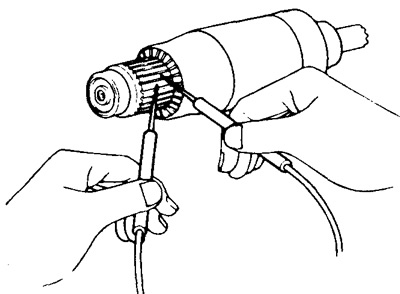
Anchor
1. Check for a short circuit between the armature winding sections by measuring the resistance between the collector plates. If there is a short circuit between the plates, then replace the anchor.
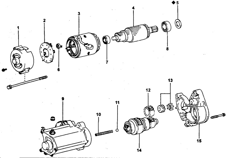
Details of a starter with a power of 1.0 kW.
1 - cover from the side of the collector,
2 - brush holder,
3 - stator,
4 - anchor,
5 - felt pad,
6 - brush spring,
7 - front bearing,
8 - rear bearing,
9 - traction relay,
10 - return spring,
11 - steel ball,
12 - parasitic gear,
13 - bearing,
14 - overrunning clutch,
15 - drive side cover,
♦ - parts that are not subject to reuse.
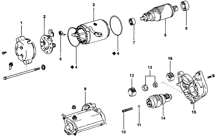
Details of a starter with a power of 1.4 kW.
1 - cover from the side of the collector,
2 - brush holder,
3 - stator,
4 - annular sealing gasket,
5 - anchor,
6 - brush spring,
7 - front bearing,
8 - rear bearing,
9 - traction relay,
10 - return spring,
11 - steel ball,
12 - parasitic gear,
13 - bearing,
14 - overrunning clutch,
15 - drive side cover
16 - gear,
♦ - non-reusable parts
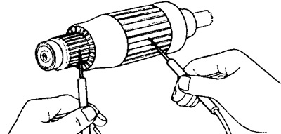
2. Check if the armature winding is shorted to ground by measuring the resistance between the collector plates and the armature core. The resistance should tend to infinity. Otherwise, replace the anchor.
Collector
1. Grind dirty or burnt surfaces with #400 sandpaper or grind on a lathe.
2. Check the runout of the collector.
- The maximum allowable radial runout is not more than - 0.05 mm
3. Measure the collector diameter.
- Nominal diameter - 30 mm
- Minimum allowable - 29 mm
If the diameter is less than the minimum value, replace the anchor.
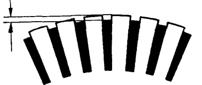
4. Check the collector lamellae by making sure that the spaces between the lamellas are free from foreign material and dirt and by measuring the height of the lamella protrusion.
- Nominal lamella protrusion height (plates) collector - 0.6 mm
- Minimum lamella protrusion height (plates) collector - 0.2 mm
Otherwise, deepen the grooves.
Stator
1. Check for an open in the stator winding circuit by measuring the resistance between the stator winding wire terminal and the brush. If the resistance tends to infinity, then replace the stator.
2. Check if the stator winding is shorted to ground by measuring the resistance between the stator windings (brushed) and hull. If there is continuity, replace the stator.
Brushes
Using a caliper, measure the height of the brushes.
Brush height:
for a 1.0 kW starter:
- nominal - 13.5 mm
- minimum allowable - 8.5 mm
for a 1.4 kW starter:
- nominal - 15.5 mm
- minimum allowable - 10.0 mm
If the measurement results are outside the specified limits, replace the brushes.
Brush springs
Using a dynamometer, measure the tension of the spring at the moment it is separated from the brush.
- The minimum allowable tension is - 1.79-2.41 kgf (18-24 N).
Note: the measurement is carried out at the moment of separation of the spring from the brush. If the tension does not match the specified values, then replace the springs.
Brush holder
Use an ohmmeter to measure the resistance between the positive and negative brush holders. In the presence of conduction (circuit is closed) replace or repair brush holders.
Freewheel and gears
1. Inspect the drive gear teeth, idler gear, and entire freewheel assembly for wear or damage. Replace worn or damaged gears, also inspecting the flywheel ring gear.
2. Check the freewheel drive gear by turning it clockwise. Make sure it spins freely.
Replace the freewheel assembly if necessary.
Bearings
1. Check the bearings by rotating each bearing by hand while pressing it axially. If resistance to rotation is felt or the bearing seizes, replace it.
2. When replacing bearings, use a suitable tool.
Traction relay
1. Check the retracting winding by measuring the resistance between the starter terminal with an ohmmeter "50" and terminal "WITH". If resistance tends to infinity (open circuit), replace the traction relay.
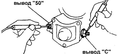
2. Check the holding winding by measuring the resistance between the starter terminal with an ohmmeter "50" and traction relay housing. If resistance tends to infinity (open circuit), replace the traction relay.