
Rotor
1. Using an ohmmeter, measure the resistance between the slip rings of the collector. Resistance value for generator without electronic regulator (cold) should lie in the range from 3.9 ohms to 4.1 ohms, and for a generator with an electronic regulator - from 2.8 to 3.0 ohms.
In the absence of conduction (resistance tends to infinity) replace the rotor.
2. Check if the excitation winding closes (rotor winding) to the mass. Using an ohmmeter, measure the resistance between the slip ring and the rotor pole piece. The resistance should tend to infinity, otherwise replace the rotor.
3. Check the outer surfaces of the slip rings. In the presence of roughness, scratches, replace the rotor. Using a caliper, measure the outside diameter of the manifold slip rings.
- Nominal - 32.3 - 32.5 mm
- Minimum allowable - 32.1 mm
If the diameter is less than the minimum value, replace the rotor.
Stator
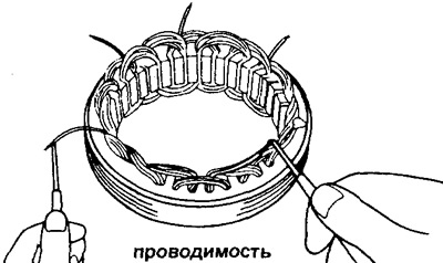
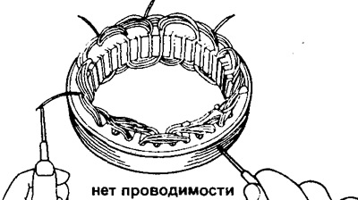
1. Using an ohmmeter, check all starter coils for open circuits. If the resistance tends to infinity, then replace the stator.
Note: in this operation, the corresponding (encountered) wire leads must be soldered.
2. Check whether the turns of the stator winding are shorted to ground. Using an ohmmeter, measure the resistance between the winding wires and the stator core. In the presence of conduction (winding shorted to ground) replace the stator.
Brushes
1. Measure the length of the protruding part of the brushes.
The nominal length of the protruding part of the brushes for the generator:
- with mechanical regulator - 12.5 mm
- with electronic regulator - 16.5 mm
The minimum allowable length of the protruding part of the brushes is 5.5 mm
If the length is less than the minimum value, replace the brushes.
2. Replace brushes (if necessary).
A) Unsolder the brush wire and remove the brush and spring.
b) Pass the brush wire (new) through a spring.
V) Install the new brush with the spring into the brush holder.
G) Solder the brush wire to the brush holder terminal so that the length of the protruding part of the brush is 12.5 mm for a generator with a mechanical voltage regulator and 16.5 mm for a generator with an electronic voltage regulator.
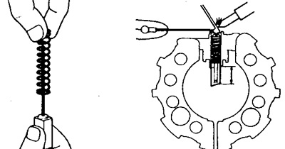
d) Check that the brush moves smoothly in the brush holder.
e) Cut off the excess part of the brush wire with wire cutters.
Rectifier block
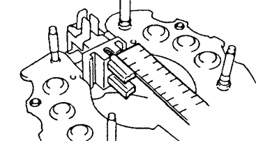
1. Check the positive valves.
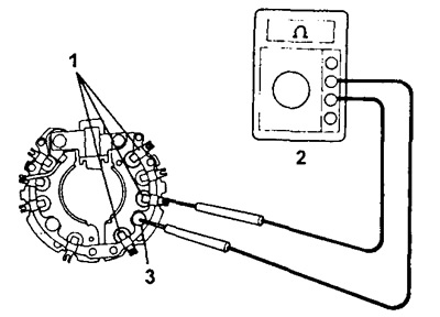
A) Connect one lead of an ohmmeter (1) to a positive conclusion (hairpin) (2) rectifier block, and the other, in turn, to other conclusions (3).
b) Reverse the polarity of the ohmmeter leads and repeat the previous procedure.
V) Make sure that in the first case the ohmmeter shows the presence of conductivity, and in the second case - its absence.
Otherwise, replace the rectifier unit.
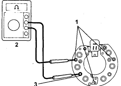
Generator models 40A and 45A.
1 - conclusions of the rectifier unit;
2 - ohmmeter;
3 - positive output of the rectifier unit (hairpin).
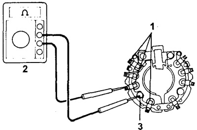
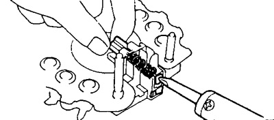
Generator models 50A and 55A.
1 - conclusions of the rectifier unit;
2 - ohmmeter;
3 - positive output of the rectifier unit (hairpin).
2. Check negative valves.
A) Connect one lead of an ohmmeter (1) to a negative conclusion (hairpin) (2) rectifier block, and the other, in turn, to other conclusions (3).
b) Reverse the polarity of the ohmmeter leads and repeat the previous procedure.
V) Make sure that in the first case the ohmmeter shows the presence of conductivity, and in the second case - its absence.
Otherwise, replace the rectifier unit.
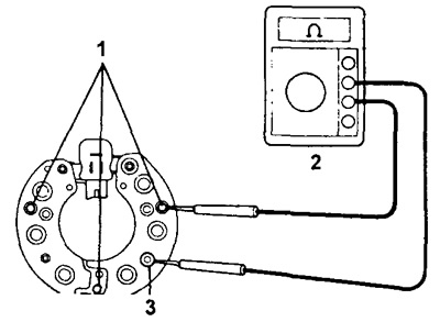
1 - generator models 40A and 45A;
2 - conclusions of the rectifier unit;
3 - ohmmeter;
4 - negative output of the rectifier unit (hairpin).
Generator models 50A and 55A.
1 - conclusions of the rectifier unit;
2 - ohmmeter;
3 - negative output of the rectifier unit (hairpin).
Bearings
Check the front and rear bearings to make sure they turn smoothly without binding. Otherwise, replace the bearings: to remove the front bearing, it is enough to remove the front cover, and to remove the rear bearing, you must use a suitable puller.