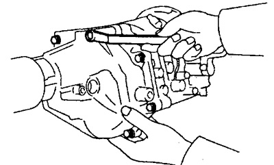
2. Remove the reversing light switch and speedometer driven gear.
3. Remove the clutch housing from the gearbox housing.
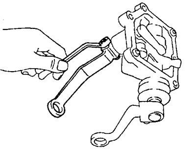
4. Remove the shift lever housing assembly.
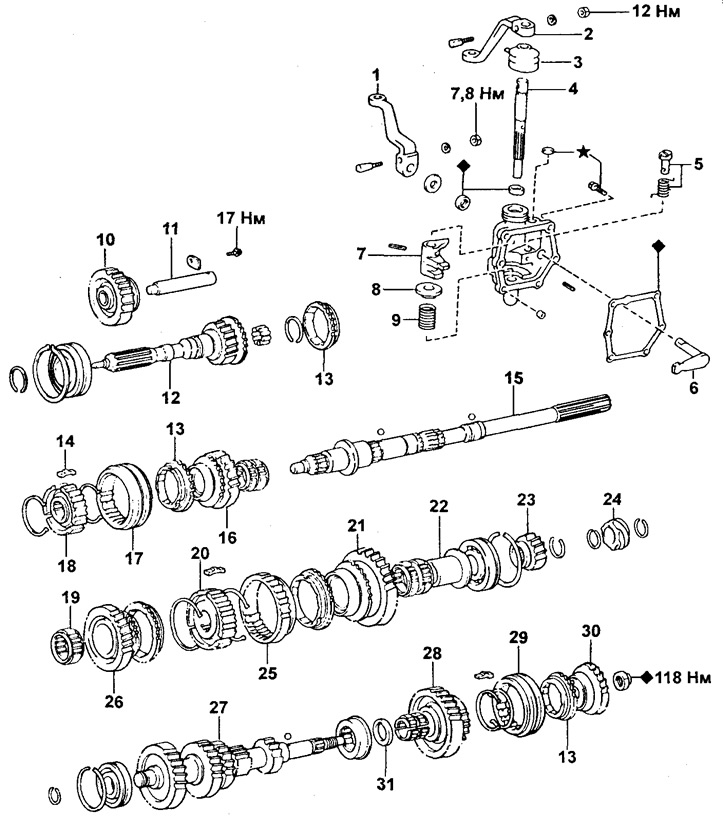
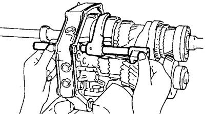
Gearbox components G55 and G56.
1 - External gear selection lever,
2 - External gear lever,
3 - Cover,
4 - Shaft for selecting and engaging gears,
5 - Locking pin for reverse gear engagement,
6 - Internal gear selection lever,
7 - Lever for selecting and engaging gears,
8 - Saddle,
9 - Spring,
10 - Intermediate reverse gear,
11 - Axis of the intermediate reverse gear,
12 - Primary shaft,
13 - Synchronizer ring,
14 - Guide key,
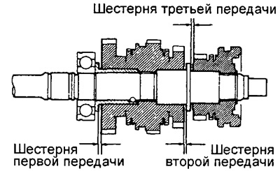
15 - Secondary shaft,
16 - Third gear,
17 - Hub coupling No. 2,
18 - Clutch hub No. 2,
19 - Needle roller bearing,
20 - Clutch hub No. 1,
21 - First gear,
22 - The inner ring of the bearing,
23 - Gear wheel of the fifth gear,
24 - Speedometer drive gear,
25 - Hub coupling No. 1,
26 - Second gear,
27 - Intermediate gear,
28 - Intermediate gear of the fifth gear,
29 - Fifth gear synchronizer clutch,
30 - Fifth gear synchronizer hub,
31 - Spacer sleeve.
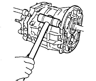
5. Remove the crankcase extension.
6. Remove the front bearing housing and use pliers to remove the circlips.
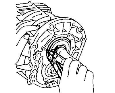
7. Disconnect the intermediate plate from the gearbox housing.
A) Using a plastic mallet, gently knock out the gearbox housing.
V) Separate the gearbox housing from the intermediate plate.
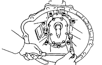
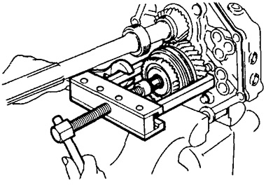
8. Clamp the intermediate plate in a vise using the two clutch housing mounting bolts, flat washers and suitable nuts.
Warning. Flat washers must be installed with the reverse side compared to their normal position. By increasing or decreasing the number of flat washers to be inserted, achieve such a position that the end face of the bolt tip and the end surface of the nut are flush with each other.
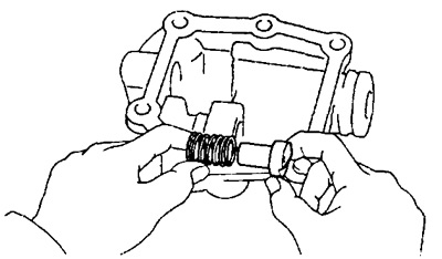
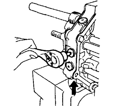
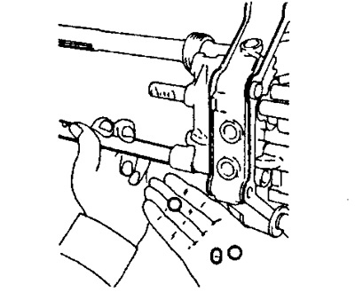
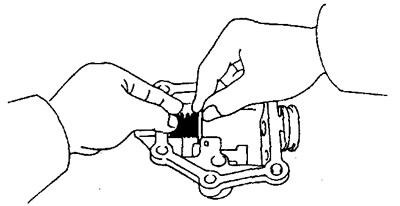
9. Turn out carving plugs, take out springs and balls of clamps.
A) Using a tool, remove the screw plugs.
b) Using a magnetic finger, remove the springs and retainer balls.
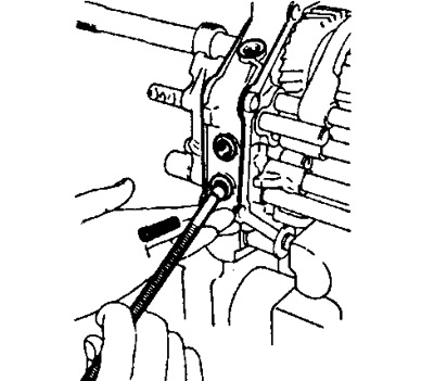
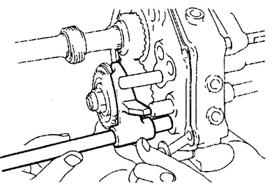
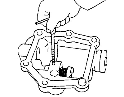
10. Remove split pin and bolt.
A) With the help of a beard with a thin cylindrical end and a hammer, knock out four pins.
b) Remove the bolt from the shift fork No. 1.
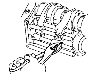
11. Using a pair of pliers, remove the four circlips on the shift fork rods.
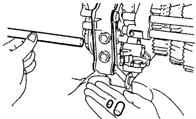
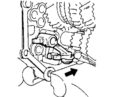
12. Remove the No. 4 shift fork rod and No. 3 shift fork.
A) Pull the #4 shift fork stem away from the intermediate plate.
Warning: Catch the balls and pin with your hand, if they do not fall out, use the magnetic finger to remove them.
b) Remove shift fork shaft No. 4 and shift fork No. 3.
13. Remove the ball and head of the reverse gear engagement rod.
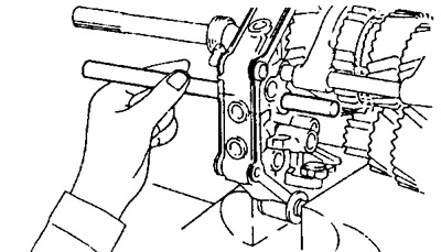
14. Remove shift fork stem No. 3.
A) Pull the #3 shift fork stem away from the intermediate plate.
Warning: Catch the pins with your hand, if they do not fall out use the magnetic finger to remove them.
b) Remove shift fork shaft No. 3.
15. Remove the No. 2 shift fork stem and No. 2 shift fork.
A) Pull the #2 shift fork stem away from the intermediate plate.
Warning: Catch the pin with your hand, if it does not fall out use the magnetic finger to remove it.
b) Remove shift fork #2 and stem.
16. Remove the shift fork rod No. 1 and the shift head of the first and second gears.
17. Remove the reverse idle gear and idle gear shaft.
A) Remove the intermediate gear axle retainer.
b) Remove the intermediate gear and its shaft.
18. Remove the backing gear from the bracket.
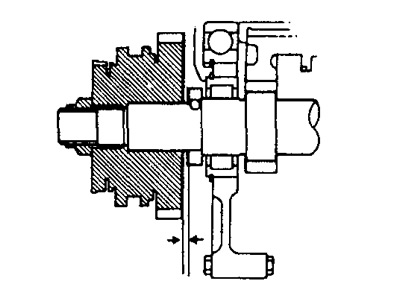
19. Measure the axial clearance of the intermediate gear of the fifth gear.
Using a set of measuring probes, measure the axial clearance of the intermediate gear of the fifth gear.
- Nominal clearance - 0.1 -0.3 mm
- Maximum clearance - 0.3 mm
20. Remove the fifth gear synchronizer hub, synchronizer ring, needle bearings and fifth gear idler with hub clutch No. 3.
A) Engage gears.
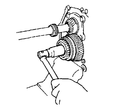
b) Loosen the nut with a hammer and chisel.
V) Remove the lock nut.
G) Disengage gears.
d) Using a puller, remove the fifth gear synchronizer hub, synchronizer ring, needle bearing and fifth gear idler.
21. Remove spacer and ball with magnetic finger.
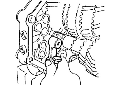
22. Turn away two bolts and remove an arm of scenes of inclusion of transfer of a backing.
23. Using the special tool, remove the four bolts and remove the rear bearing housing.
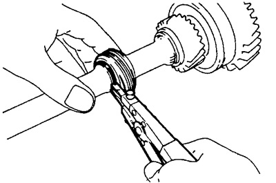
24. Use a pair of pliers to remove the retaining ring.

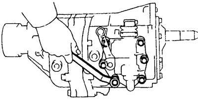
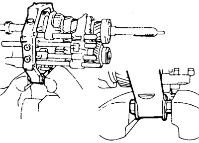
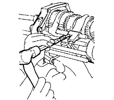
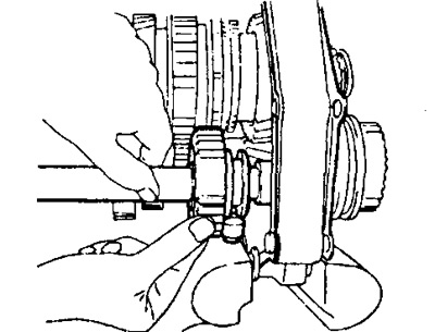
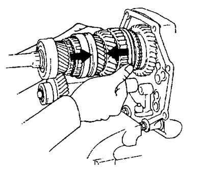
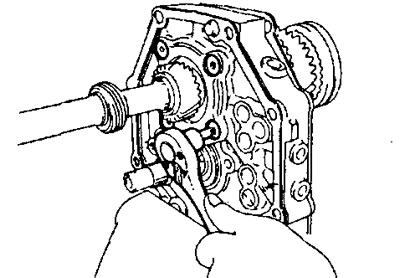
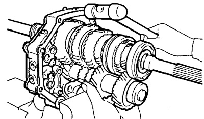
25. Take out a secondary shaft, an intermediate shaft and an input shaft as one assembly unit from an intermediate plate.
A) Remove the output shaft, intermediate shaft and input shaft from the intermediate plate as follows: pull the intermediate shaft towards you and hit the intermediate plate with a plastic hammer as shown in the figure.
b) Remove the input shaft with the 13 roller needle roller bearing from the output shaft.
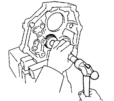
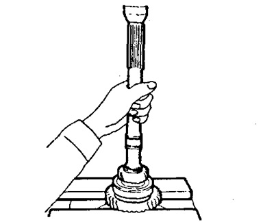
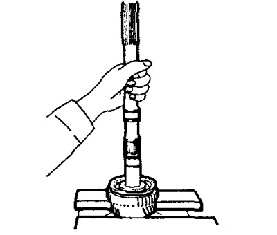
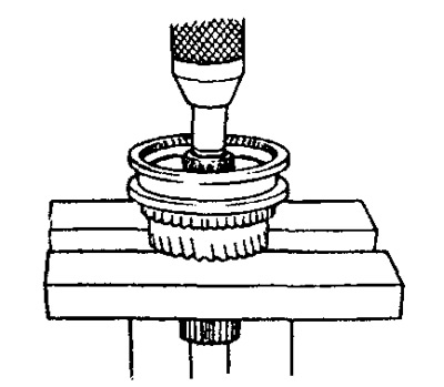
26. Use a punch and hammer to drive the intermediate shaft bearing out of the plate.
27. Remove the speedometer drive gear.
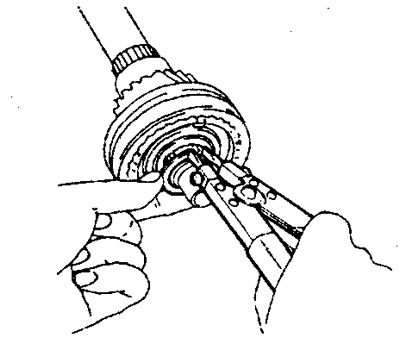
A) Remove the retaining ring using pliers.
b) Remove the speedometer drive gear.
V) Use the magnetic finger to remove the steel ball.
G) Remove the retaining ring using pliers.
28. Measure the end play of each gear.
- Nominal clearance - 0.10 - 0.25 mm
- Maximum clearance - 0.25 mm
29. Remove the fifth gear, bearing, first gear, bearing inner race, and needle roller bearing.
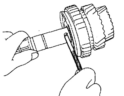
A) Using two screwdrivers and a hammer, remove the circlip.
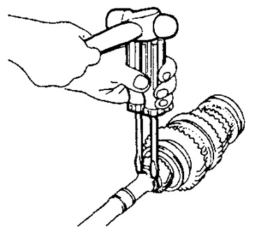
b) Using a press, remove the 5th gear, bearing, 1st gear and bearing inner race.
G) Remove the needle roller bearing.
30. Remove the synchronizer ring.
31. Using a magnetic finger, remove the retainer ball.
32. Remove the No. 1 hub clutch assembly with the second gear.
A) Using a press, remove the No. 1 hub clutch, synchronizer ring, and second gear.
b) Remove the needle bearing.
33. Remove the No. 2 hub clutch assembly with the third gear.
A) Remove the retaining ring using pliers.
b) Using a press, remove the No. 2 hub clutch, synchronizer ring, and third gear.
V) Remove the needle bearing.
34. Remove the outer selector lever and shaft.
A) Remove lock pin and nut.
b) Remove the outer selector lever and shaft from the selector housing.
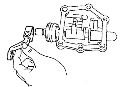
35. Remove the shift lever and cover.
36. Remove the gear selection and engagement lever and shaft.
A) Use a hammer and punch to knock out the pin.
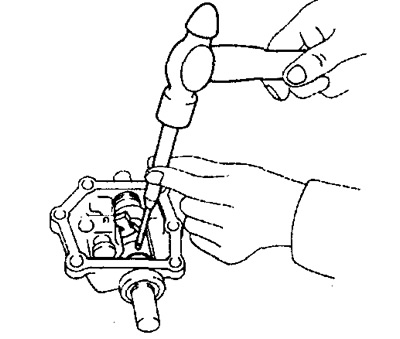
b) Remove the gear selection and engagement lever and shaft.
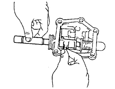
37. Remove seat and spring.
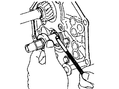
38. Remove the reverse gear lock pin and spring.
A) Screw the special tool into the pin and pull it out.
b) Remove the reverse gear lock pin and spring.