
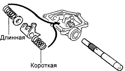
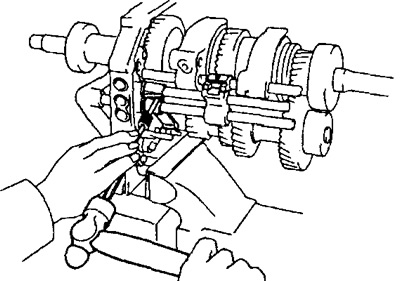
2. Install the gear selection and engagement lever and shaft.
A) Install the gear selector lever, two springs and seat.
b) Install the shaft.
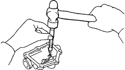
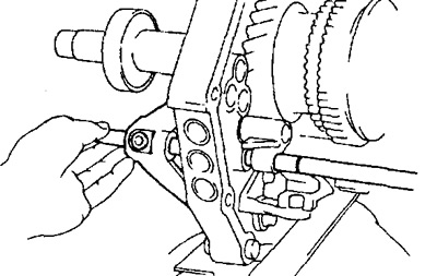
V) Using a hammer and special tool, screw in the split pin.
3. Install the outer shift lever and boot. Insert the pin and tighten the nut.
4. Install the outer and inner selector levers.
A) Install the inner selector lever.
b) Install the outer selector lever and washer.
V) Install the pin and tighten the nut.
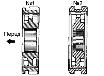
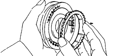
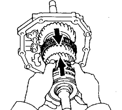
5. Insert the hubs of couplings No. 1 and No. 2 inside the hub bushings and insert the synchronizer crackers into their grooves. Install the springs under the synchronizer crackers.
Warning: It is necessary to install the springs under the synchronizer crackers in such a way that the end of one spring does not coincide with the end of the other spring.
6. Install the 3rd gear and No. 2 hub clutch onto the output shaft.
A) Apply gear oil to the shaft and needle bearing.
b) Put the synchronizer ring on the gear and align the grooves in the ring with the synchronizer crackers.
V) Insert the needle bearing into the third gear.
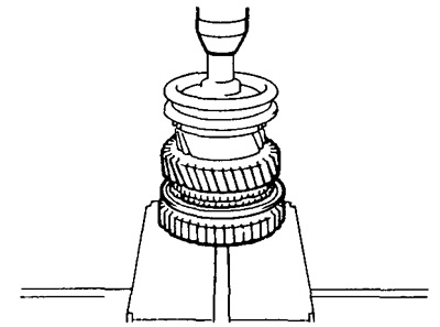
G) Using a press, install the third gear and the No. 2 hub clutch.
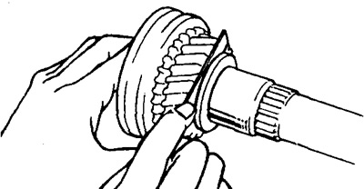
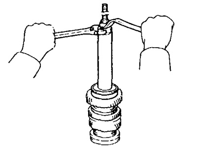
7. Install retaining ring.
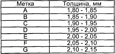
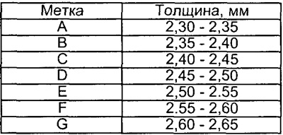
A) Select the retaining ring for minimum end play and install it on the shaft.
8. Measure third gear end play.
- Nominal clearance - 0.1 -0.25 mm
9. Install the 2nd gear and No. 1 hub clutch.
A) Apply gear oil to the shaft and needle bearing.
b) Put the synchronizer ring on the gear and align the grooves in the ring with the synchronizer crackers.
V) Insert the needle bearing into the second gear.
G) Using a press, install the third gear and the No. 2 hub clutch.
10. Install retaining ring.
A) Select the retaining ring for minimum end play and install it on the shaft.
11. Install spacer and first gear.
A) Install the spacer sleeve on the output shaft.
b) Apply gear oil to the needle bearing.
V) Assemble the first gear, synchronizer ring and needle bearing.
G) Install the assembly unit on the secondary shaft and align the grooves in the ring with the synchronizer crackers.
12. Install the first gear thrust washer on the output shaft and align with the pin.
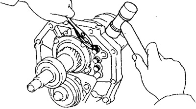
13. Using the special tool, install the output shaft center bearing.
14. Measure the axial clearance of the first and second gears.
Rated Clearance:
- First gear - 0.10-0.45 mm
- Second gear - 0.10-0.25 mm
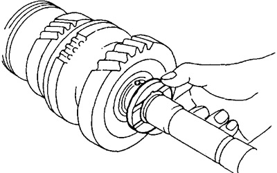
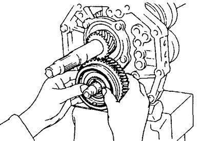
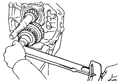
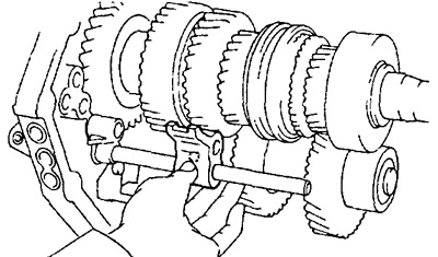
15. Install the fifth gear with the special tool and a press.
16. Install the output shaft in the intermediate plate by pushing in the output shaft and lightly tapping the intermediate plate. Put on retaining rings.
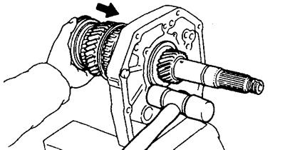
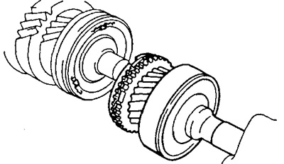
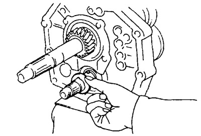
17. Install input shaft.
A) Apply gear oil to the needle bearing and install it on the input shaft.
b) Push the input shaft onto the secondary shaft, ensuring that the grooves of the synchronizer ring match the synchronizer crackers.
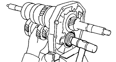
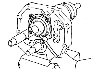
18. Install the intermediate shaft.
19. Establish an arm of scenes of inclusion of transfer of a backing and tighten bolts.
- Tightening torque - 18 Nm
20. Establish a scene of inclusion of transfer of a backing on an arm.
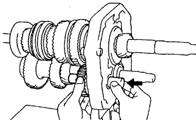
21. Install the reverse idle gear and shaft.
A) Align the reverse gear pin with the idler gear groove and insert the shaft into the intermediate plate.
22. Install the rear bearing housing.
A) Align the rear bearing housing with the idler gear shaft groove and tighten the bolts.
- Tightening torque - 18 Nm
23. Insert the 5th idle gear into the No. 3 hub clutch.
A) Install the synchronizer lugs and the No. 3 hub clutch onto the 5th idle gear.
b) Install the springs under the synchronizer crackers.
Warning: It is necessary to install the springs under the synchronizer crackers in such a way that the end of one spring does not coincide with the end of the other spring.
24. Install ball and thrust washer.
25. Install the 5th idle gear with the No. 3 hub clutch assembly and needle bearing.
A) Apply gear oil to the needle bearing.
b) Install the 5th idle gear with the No. 3 hub clutch and needle bearing.
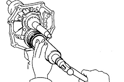
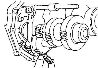
26. Install the synchronizer ring and fifth gear synchronizer hub.
A) Install the synchronizer ring on the synchronizer hub.
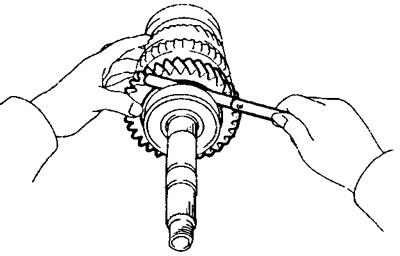
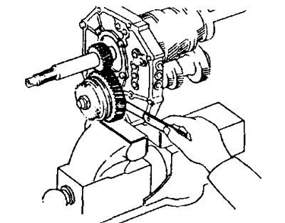
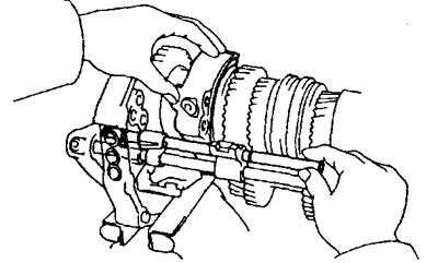
b) Using a press and a tool head, press in the fifth gear synchronizer hub so that the grooves of the synchronizer ring exactly match the synchronizer crackers.
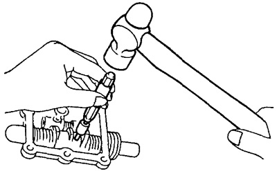
Note: After installing the 5th gear synchronizer hub, gently hit it as shown in the figure, applying a load of 1.5-2.0 kg.
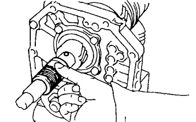
27. Install the lock nut.
A) Engage gears.
b) Install and tighten the lock nut.
- Tightening torque - 127 Nm
V) Using a hammer and chisel, caulk the lock nut.
G) Disengage gears.
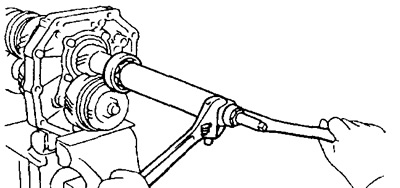
28. Measure the axial clearance of the intermediate gear of the fifth gear.
- Nominal clearance - 0.10 - 0.35 mm
29. Install the ball and speedometer drive gear.
30. Using the special tool, install the output shaft rear bearing.
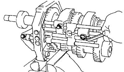
31. Install the No. 4 shift fork rod, reverse gear shift rod head, and No. 3 shift fork.
A) Install the No. 3 shift fork into the No. 3 hub clutch groove.
b) Insert the No. 4 shift fork shaft into the shift fork through the intermediate plate and put on the reverse gear fork.
V) Install the reverse gear shift rod head and detent ball to the No. 4 shift fork stem.
32. Install shift fork stem No. 3.
A) Using a magnetic finger and a screwdriver, install the locking ball into the intermediate plate.
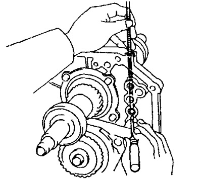
b) Install the pin in the shaft hole.
V) Insert the No. 1 shift fork into the No. 1 hub clutch groove.
G) Insert the No. 3 shift fork stem through the reverse shift fork and intermediate plate.
33. Install shift fork stem #2, shift fork and stem head.
A) Using a magnetic finger and a screwdriver, install the locking ball into the intermediate plate.
b) Install the pin in the shaft hole.
V) Insert shift fork #2 into hub #2 clutch groove.
G) Insert the No. 2 shift fork stem through the No. 1 and No. 2 shift forks and the spacer plate.
34. Install split pins into stem head and reverse gear fork.
35. Install shift fork shaft No. 1.
A) Using a magnetic finger and a screwdriver, install the locking ball into the intermediate plate.
b) Insert the #1 shift fork stem through the #1 shift fork and intermediate plate.
36. Check gear shift.
A) Engage first gear.
b) The shafts of the shift forks No. 2, 3, 4 must not move.
37. Install retaining rings with a hammer and round nose pliers.
38. Wrap fastening bolts.
- Tightening torque - 20 Nm
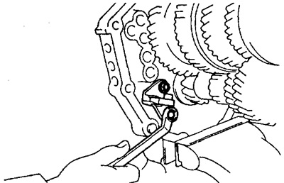
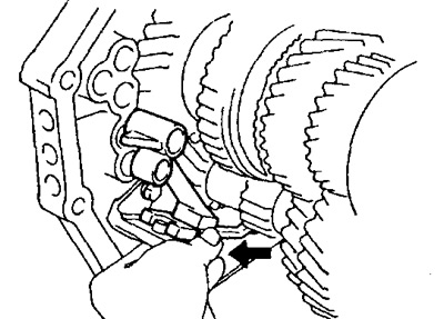
39. Install retainer balls, springs and screw plugs.
A) Apply sealant to the screw plugs.
b) Install the retainer balls, screw plugs and tighten them with the special tool.
- Tightening torque - 19 Nm
40. Install the magnet in the intermediate plate.
41. Open the vise, remove the intermediate plate and remove the bolts, nuts and washers.
42. Install the gearbox housing,
A) Apply sealant as shown.
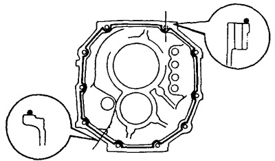
b) Install the crankcase on the intermediate plate. Use a hammer if necessary.
43. Establish lock rings of forward bearings of primary and intermediate shaft by means of round nose pliers.
44. Install the front bearing housing.
A) Apply sealant to the housing as shown in the illustration and install it on the gearbox housing.
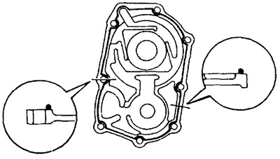
b) Apply sealant to the bolts and tighten them.
- Tightening torque - 17 Nm
45. Install extension housing.
A) Apply sealant to the extension housing and screw it to the intermediate plate.
- Tightening torque - 37 Nm
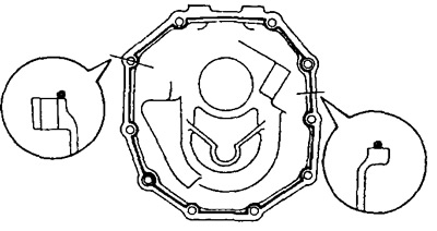
46.Install the side cover.
Apply sealant as shown in the illustration and screw onto the gearbox housing.
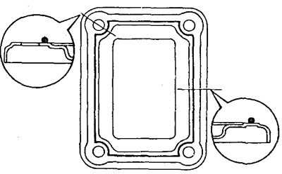
47. Establish the case of the mechanism of switching.
A) Apply sealant as shown.
b) Apply sealant to the bolts and screw the housing to the gearbox housing.
- Tightening torque - 17 Nm
48. After installing the shift housing, check the following:
A) That the primary and secondary shafts rotate smoothly.
b) That switching can be smoothly carried out in all positions.
49. Install the clutch housing.
A) Install the clutch housing and tighten the bolts.
- Tightening torque - 36 Nm
50. Install the reversing light switch.
- Tightening torque - 44 Nm
51. Install the speedometer driven gear.
52. Install the release fork and bearing.
Apply grease to the surface of the following parts:
- Release fork and hub in the places of their contact with each other.
- Release fork and pusher in the places of their contact with each other.
- Release fork mounting hinge.
- Splined part of the clutch disc.