



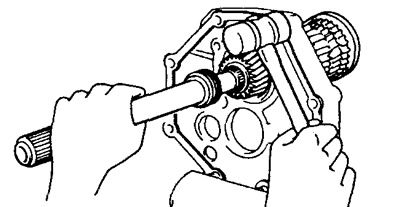
2. Install the input shaft.
a) Apply grease to the 13-roller needle roller bearing and insert it into the input shaft.
b) Place the primary shaft on the secondary shaft, ensuring that the grooves of the synchronizer ring match the synchronizer crackers.
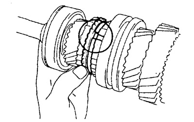
3. Install the idler gear into the idler plate while holding the idler gear and installing the idler gear rear bearing.
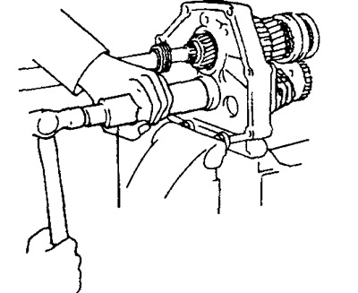
4. Using round-nose pliers, install the bearing retaining ring.
Note: It is imperative to ensure that the retaining ring is flush with the surface of the intermediate plate.
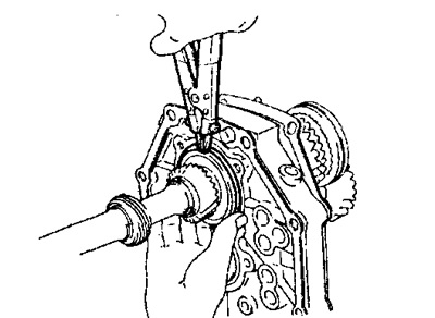
5. Install the rear bearing housing and tighten the screws.
- Tightening torque: 18 Nm
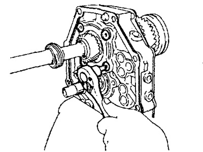
6. Install the reverse gear lever bracket and tighten the bolts.
- Tightening torque - 18 Nm
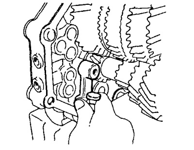
7. Install the ball and spacer sleeve.
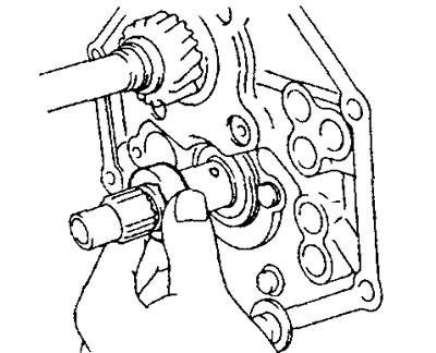
8. Insert the fifth gear intermediate gear into the coupling of hub No.3.
a) Install the synchronizer crackers and hub sleeve No.3 on the fifth gear intermediate gear.
b) Install the springs under the synchronizer crackers.
Note: The springs must be installed under the synchronizer crackers in such a way that the end of one spring does not coincide with the end of the other spring.
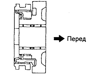
9. Install the fifth gear idler gear with the #3 hub bushing assembly and needle roller bearings.
a) Apply transmission oil to the needle bearing rollers.
b) Install the fifth gear intermediate gear with hub sleeve No.3 and needle roller bearings.
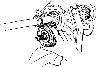
10. Install the synchronizer ring and the fifth gear synchronizer hub.
a) Place the synchronizer ring on the fifth gear synchronizer hub.
b) Using a press and a 22 mm socket wrench, press in the fifth gear synchronizer hub so that the grooves in the synchronizer ring exactly match the synchronizer crackers.
Note: After installing the fifth gear synchronizer hub, gently hit it as shown in the figure, creating a load of 1.5 - 2.0 kg.
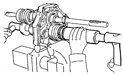
11. Install the lock nut.
a) Engage the gears.
b) Install and tighten the lock nut.
- Tightening torque - 118 Nm
c) Coal the lock nut.
d) Disengage the gears.
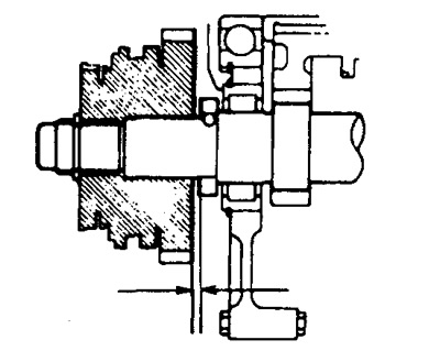
12. Measure the axial clearance of the fifth gear intermediate gear.
- Normal clearance is 0.10-0.30 mm
13. Install the reverse gear selector lever onto the bracket.
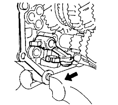
14. Install the reverse gear intermediate gear.
a) Install the reverse intermediate gear onto the shaft.
b) Align the reverse gear selector pin with the groove of the reverse gear intermediate gear and insert the intermediate gear shaft into the intermediate plate.
c) Install the intermediate gear shaft lock and tighten the bolt.
- Tightening torque - 17 Nm
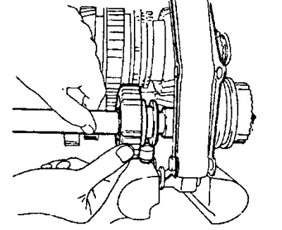
15. Install the No.1 gear shift fork into the groove of the No.1 hub coupling and insert the gear shift fork rod into the fork through the intermediate plate and put on the first and second gear shift head.
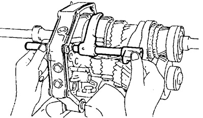
16. Install the pins.
a) Apply grease to the pins.
b) Using a magnetic pin and a screwdriver, install the pin into the intermediate plate.
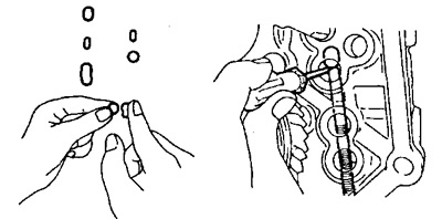
17. Install the shift fork rod No.2 and shift fork No.2.
a) Install the pin into the shaft hole.
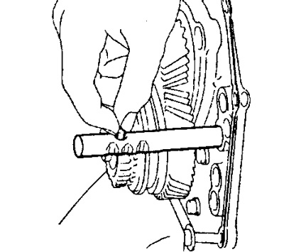
b) Install the No.2 shift fork into the groove of the No.2 hub coupling and insert the No.2 shift fork rod into the aligned holes of the shift fork and the intermediate plate.
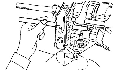
18. Using a magnetic finger and a screwdriver, install the pin into the spacer plate.
19. Install gear shift rod No.3.
a) Install the pin into the shaft hole.
b) Install the gear shift fork rod and the head of the reverse gear engagement rod onto the reverse gear engagement linkage through the intermediate plate.
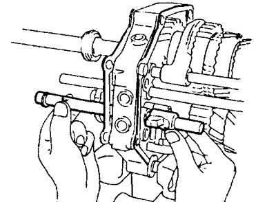
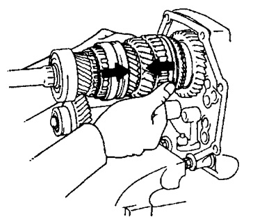
20. Install shift fork rod #4, shift fork #3 and detent balls.
a) Move the hub sleeve as shown in the figure.
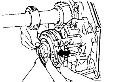
b) Install the shift fork No.3 into the groove of the hub sleeve No.3 and insert the shift fork rod No.4 into the shift fork No.3.
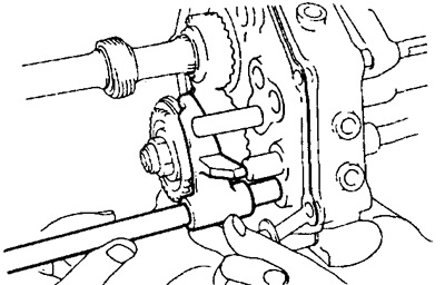
c) Using a magnetic pin and a screwdriver, insert the detent ball into the intermediate plate and install the shift fork rod No.4 into the intermediate plate.
d) Using a magnetic pin and a screwdriver, insert the locking ball into the hole in the head of the reverse gear engagement rod and install the rod of gear shift fork No.4 into the head of the rod.
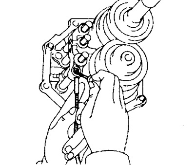
21. Checking gear shifting.
a) Engage first gear.
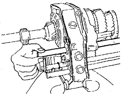
b) The rods of gear shift forks No.2, 3, 4 should not move.
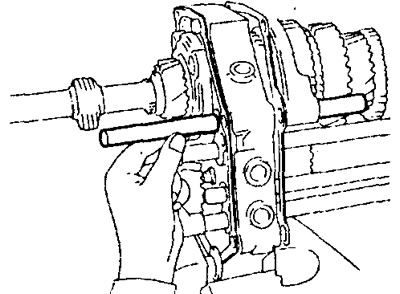
22. Install the split pin and bolt.
a) Using a special tool and a hammer, insert the split pin into the reverse gear engagement linkage, reverse gear engagement head and gear shift forks No.2, 3.
b) Install and tighten the bolt on shift fork No.1.
- Tightening torque - 20 Nm
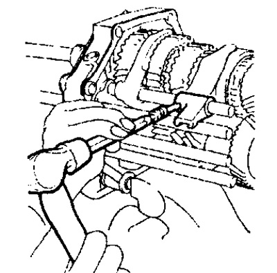
23. Using round-nose pliers and a hammer, install the four shift fork rod retaining rings.
24. Install the retainer balls, springs and threaded plugs.
a) Apply sealant to the threaded plugs.
b) Install the locking balls, threaded plugs and tighten them with a special tool.
- Tightening torque - 19 Nm
Note: Install the short spring on the bottom of the intermediate plate.
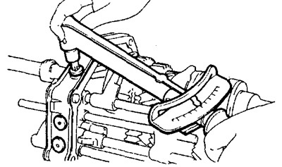
25. Release the vice, remove the intermediate plate and remove the bolts, nuts and washers.
26. Install the gearbox housing onto the intermediate plate with a new gasket.
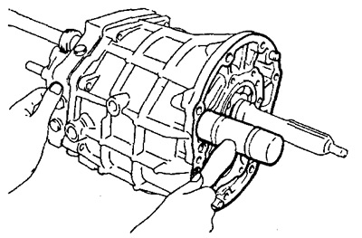
27. Using round-nose pliers, install the two bearing retaining rings.
28. Install the front bearing housing with a new gasket, apply sealant to the threaded parts of the bolts. Screw in the bolts and tighten them.
- Tightening torque - 17 Nm
29. Install the crankcase extension with a new gasket and tighten the bolts.
- Tightening torque - 37 Nm
30. Install the shift mechanism housing assembly with a new gasket and tighten the bolts.
- Tightening torque - 17 Nm
31. After installing the shift mechanism housing, check the following:
a) That the primary and secondary shafts rotate smoothly.
b) That switching can be carried out smoothly in all positions.
32. Install the clutch housing.
a) Install the clutch housing and tighten the bolts.
- Tightening torque - 37 Nm
33. Install the reversing light switch.
- Tightening torque - 37 Nm
34. Install the speedometer drive driven gear.
35. Install the release fork and bearing.
Apply consistent grease to the surface of the following parts:
- The release fork and hub at the points of their contact with each other.
- The release fork and pusher at the points of their contact with each other.
- Release fork mounting hinge.
- Splined part of the clutch disc.