2. Remove the reversing light switch and speedometer driven gear.
3. Remove the clutch housing from the gearbox housing.
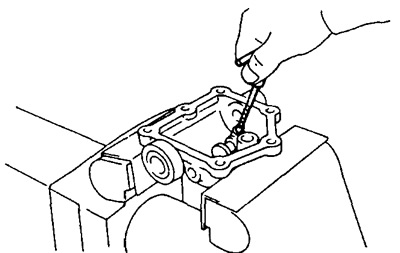
4. Remove the gearshift housing assembly with a plastic hammer after removing the six bolts.
5. Remove the crankcase extension with a plastic hammer, having previously unscrewed ten bolts.
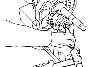
6. Remove the front bearing housing with a plastic hammer, having previously unscrewed the eight bolts.
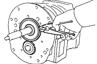
7. Use pliers to remove the circlips.
8. Remove the side cover with a plastic hammer, having previously unscrewed the four bolts.
9. Disconnect the intermediate plate from the gearbox housing
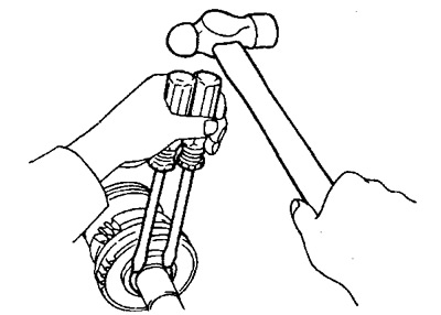
A) Using a hammer and drift, carefully remove the gearbox housing.
V) Separate the gearbox housing from the intermediate plate.
10. Remove the magnet from the intermediate plate.
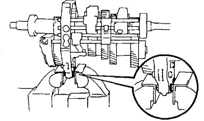
11. Clamp the intermediate plate in a vise using the two clutch housing mounting bolts, flat washers and suitable nuts.
Warning. Flat washers must be installed with the reverse side compared to their normal position. By increasing or decreasing the number of flat washers to be inserted, achieve such a position that the end face of the bolt tip and the end surface of the nut are flush with each other.
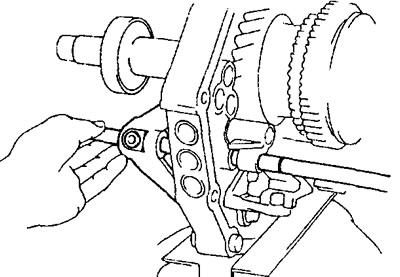
12. Turn out carving plugs, take out springs and balls-clamps.
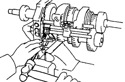
A) Using a tool, remove the screw plugs.
b) Using a magnetic finger, remove the springs and balls - clamps.
13. Remove the mounting bolts.
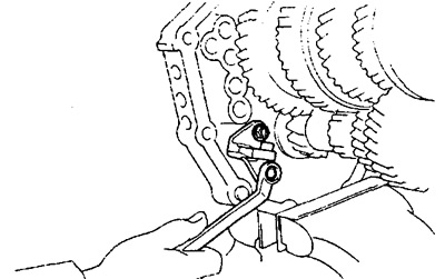
14. Using two screwdrivers and a hammer, remove the seven circlips.
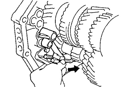
15. Remove shift fork stem No. 1.
A) Remove the shift fork shaft No. 1 from the intermediate plate.
b) Using a magnetic finger, remove the spring and balls.
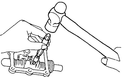
16. Using the special tool, remove the split pin.
17. Remove the No. 2 shift fork stem, shift fork, and stem head.
A) Remove the No. 2 shift fork stem from the intermediate plate.
b) Remove shift fork #2 and stem head.
V) Using a magnetic finger, remove the pins from the intermediate plate.
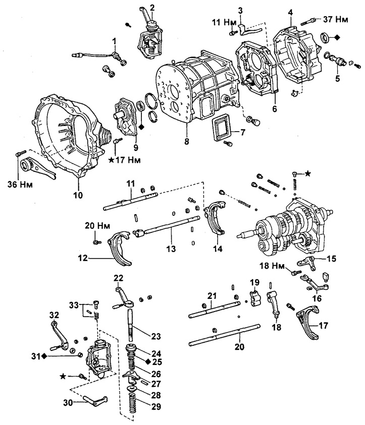
Transmission. Type R452 and R453.
1 - Reversing light switch,
2 - Switch mechanism housing,
3 - Oil receiver,
4 - Extension housing,
5 - Driven gear of the speedometer drive,
6 - Intermediate plate,
7 - Side cover,
8 - Carter box,
9 - Front bearing housing,
10 - Clutch housing,
11 - Rod shift fork No. 1,
12 - Gearshift fork No. 2,
13 - Rod shift fork No. 2,
14 - Gearshift fork No. 1,
15 - Bracket for reverse gear,
16 - Backstage engagement switch,
17 - Gearshift fork No. 3,
18 - Reverse gear engagement fork,
19 - Head of the reverse gear engagement rod,
20 - Rod shift fork No. 4,
21 - Rod shift fork No. 3,
22 - External gear lever,
23 - Shaft for selecting and shifting gears,
24 - Cover,
25 - Oil seal,
26 - Spring,
27 - Lever for selecting and engaging gears,
28 - Saddle,
29 - Spring,
30 - Internal gear selection lever,
31 - Oil seal,
32 - External gear selection lever,
33 - Locking pin for reverse gear and spring.
18. Remove the No. 3 shift fork stem and No. 1 shift fork.
A) Remove the No. 3 shift fork stem from the intermediate plate.
b) Remove shift fork No. 1.
V) Using a magnetic finger, remove the pins and retainer balls from the intermediate plate.
19. Remove the reverse gear engagement rod head and detent ball.
20. Remove shift fork stem #4 and shift fork #3.
A) Remove the No. 4 shift fork stem from the intermediate plate.
b) Remove shift fork No. 3.
21. Remove the reverse gear engagement link from the bracket.
22. Turn away two bolts and remove an arm of a stage of inclusion of transfer of a backing.
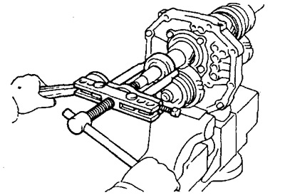
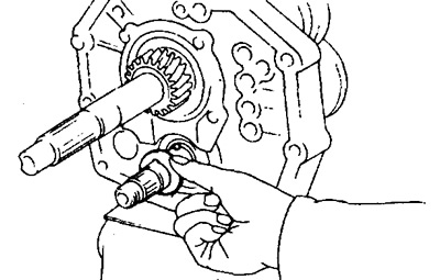
23. Using a puller, remove the rear output shaft bearing.
24. Remove the speedometer drive gear and ball.
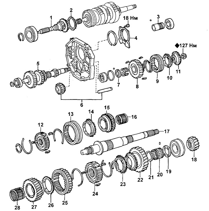
Gearbox components R452 and R453.
1 - Primary shaft,
2, 10, 14, 23, 26 - Synchronizer ring,
3 - Speedometer drive gear,
4 - Rear bearing housing,
5 - Intermediate shaft,
6 - Intermediate reverse gear and shaft,
7 - Thrust washer,
8 - Intermediate gear of the fifth gear,
9 - Hub coupling No. 3,
11 - Fifth gear synchronizer hub,
12 - Clutch hub No. 2,
13 - Hub coupling No. 3,
15 - Third gear,
16, 20, 28 - Needle bearing,
17 - Secondary shaft,
18 - Gear wheel of the fifth gear,
19 - Thrust washer,
21 - Spacer sleeve,
22 - First gear,
24 - Clutch hub No. 1,
25 - Reverse gear,
27 - Second gear.
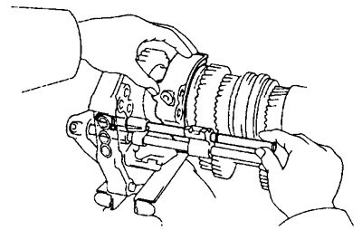
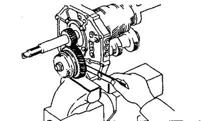
25. Measure the axial clearance of the intermediate gear of the fifth gear.
Using a set of measuring probes, measure the axial clearance of the intermediate gear of the fifth gear.
- Nominal clearance - 0.1-0.35 mm
- Maximum clearance - 0.4 mm
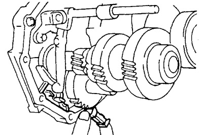
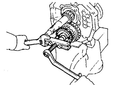
26. Remove the fifth gear synchronizer hub, synchronizer ring, needle bearings and fifth gear idler with hub clutch No. 3.
A) Engage gears.
b) Loosen the nut with a hammer and chisel.
V) Remove the lock nut.
G) Disengage gears.
d) Using a puller, remove the fifth gear synchronizer hub.
e) Remove the 5th idle gear and the No. 3 hub clutch.
27. Remove thrust washer and ball.
28. Turn away four bolts and remove a cover of the back bearing.
29. Remove the reverse gear and shaft.
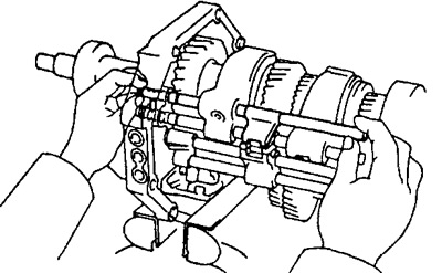
30. Using pliers, remove the bearing circlip.
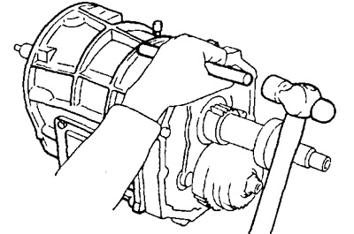
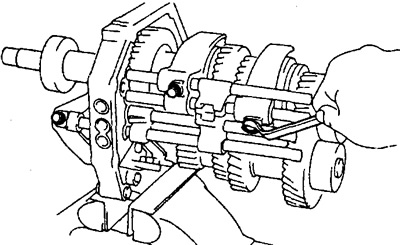
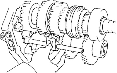
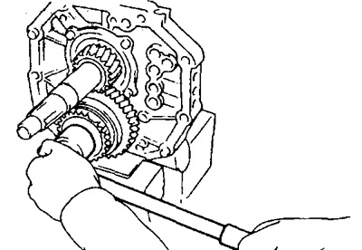
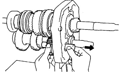
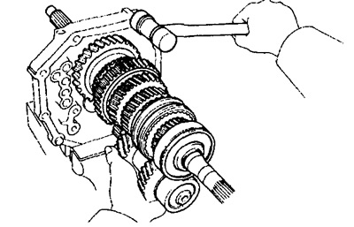
31. Take out a secondary shaft, an intermediate shaft and an input shaft as one assembly unit from an intermediate plate.
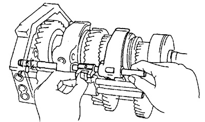
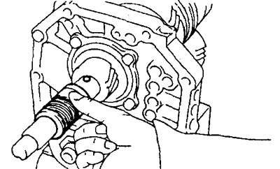
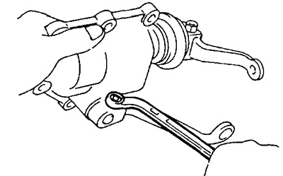
A) Remove the output shaft, intermediate shaft and input shaft from the intermediate plate as follows: pull the intermediate shaft towards you and hit the intermediate plate with a plastic hammer as shown in the figure.
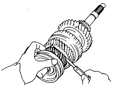
b) Remove the input shaft with the 13 roller needle roller bearing from the output shaft.
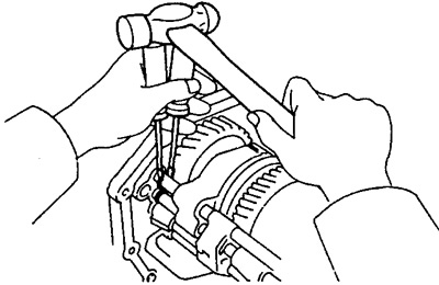
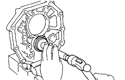
32. Use a drift and hammer to drive the intermediate shaft bearing out of the plate.
33. Measure the end play of each gear.
First gear:
- Nominal clearance - 0.10-0.45 mm
- Maximum clearance - 0.50 mm
Second and third gears:
- Nominal clearance - 0.10-0.25 mm
- Maximum clearance - 0.30 mm
34. Remove the fifth gear, center bearing and first gear.
A) Using a press, remove the 5th gear, center bearing, thrust washer, and 1st gear.
b) Remove the synchronizer ring.
V) Remove pin and needle bearing.
G) Remove the spacer sleeve.
35. Remove the No. 1 hub clutch and second gear assembly.
A) Using two screwdrivers and a hammer, remove the circlip.
b) Using a press, remove the No. 1 hub clutch, synchronizer ring, and second gear.
V) Remove the needle bearing.
36. Remove the No. 2 hub clutch and third gear assembly.
A) Remove the retaining ring using pliers.
b) Using a press, remove the No. 2 hub clutch, synchronizer ring, and third gear.
V) Remove the needle bearing.
37. Remove the outer and inner selector lever.
A) Remove the lock pin and unscrew the nut.
b) Remove the outer and inner selector lever.
38. Remove lock pin, outer shift lever and boot.
39. Remove a shaft of a choice and inclusion of transfers.
A) Using the special tool, remove the split pin.
b) Remove a shaft of a choice and inclusion of transfers.
V) Remove the gear selection and engagement lever, two springs and seat.
40. Remove the reverse lock pin and spring.
A) Using the special tool and a hammer, remove the split pin.
b) Remove the reverse lock pin and spring.