



Contents: Removal ↓ Installation ↓
Removal
1. Remove the rear wheel.
- Tightening torque - 105 Nm
2. Loosen the lock nut.
a) Remove the cotter pin and lock nut cap.
b) Loosen the lock nut by pressing the brake pedal.
- Tightening torque - 220 Nm
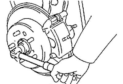
3. Remove the caliper and brake disc.
a) Unscrew the two bolts and remove the caliper.
- Tightening torque - 47 Nm
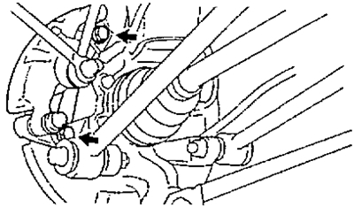
b) Hang the caliper on the wire. Do not disconnect the brake hose.
c) Remove the brake disc.
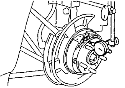
4. Check the bearing axial clearance and hub runout.
a) Using a dial indicator, check the bearing axial clearance.
- Maximum gap - 0.05 mm
If the clearance is not within specification, replace the bearing.

b) Using an indicator, check the hub runout.
- Maximum runout - 0.07 mm
If the runout is not within specifications, replace the hub and bearing.
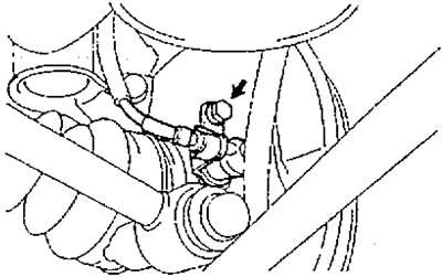
5. Remove the speed sensor
(ABS)
- Tightening torque - 20 Nm
6. Remove the parking brake shoes (see the relevant section in Chapter "Brake system").
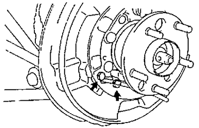
7. Loosen the bolts and disconnect the parking brake cable.
- Tightening torque - 8 Nm
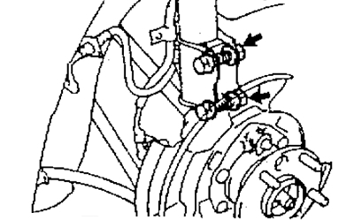
8. Unscrew the two nuts from the bottom of the rack.
Note: Do not remove the bolts.
- Tightening torque - 260 Nm
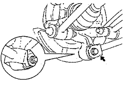
9. Loosen the bolt and disconnect the trailing arm from the knuckle.
- Tightening torque - 125 Nm
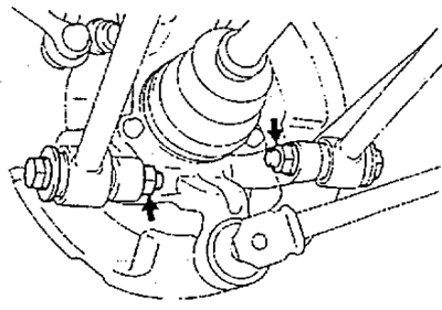
10. Unscrew the nuts and disconnect the lower arms No.1 and No.2 from the knuckle.
- Tightening torque - 125 Nm
11. Remove the rear wheel hub and knuckle assembly.
a) Remove the bolts from the bottom of the rack.
b) Remove the rear wheel hub and knuckle.
Note: Do not damage the dust cover, oil seal and rotor of the speed sensor (ABS).
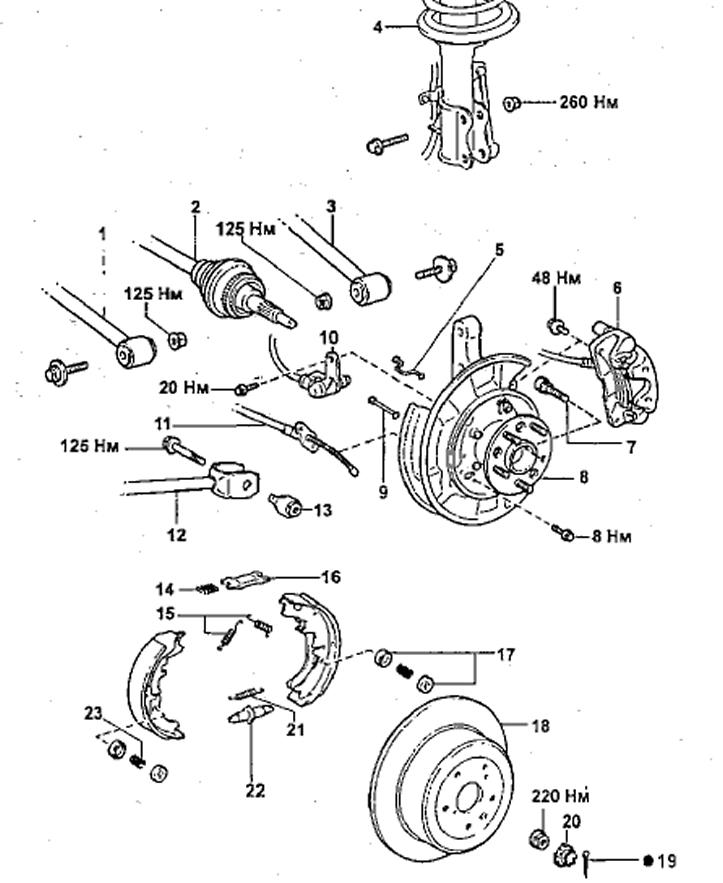
Removal the rear wheel hub and knuckle (4WD)
1 - lower suspension arm No.1,
2 - drive shaft,
3 - lower suspension arm No.2,
4 - rear suspension strut,
5, 9 - holder,
6 - support,
7 - hub bolt,
8 - hub assembly with knuckle,
10 - rotation speed sensor (ABS),
11 - parking brake cable,
12 - longitudinal lever,
13 - nut,
14 - spring,
15, 21 - brake shoe tension spring,
16 - spacer plate,
17 - spring seat,
18 - brake disc,
19 - cotter pin,
20 - lock nut cap,
22 - regulator,
23 - holder spring.
Installation
1. Installation is carried out in the reverse order of removal.
2. Tightening the bolts securing the lower and longitudinal arms to the knuckle is done after the suspension has been stabilized. In order to finally tighten the nuts securing the arms, it is necessary to jack up the knuckle.