1. Disconnect the negative plug from the storage battery.
2. Drain the engine coolant.
3. Remove the timing belt (see section "timing belt").
4. Remove the distributor (4S-FE) or combined ignition unit (3S-FE).
5. Disconnect the accelerator cable.
6. Disconnect throttle control cable (automatic transmission).
7. Remove the accelerator cable bracket.
8. Disconnect the vacuum hoses.
9. Disconnect the wiring harness.
10. Remove the generator in gathering and an adjusting lath of the generator.
11. Disconnect the radiator inlet hose.
12. Disconnect the fuel inlet hose and fuel return hose.
13. Disconnect the coolant bypass hose.
14. Disconnect the heater outlet hose.
15. Disconnect the coolant bypass tube.
16. Remove the vacuum reservoir stand #2.
17. Disconnect a reception pipe of system of release.
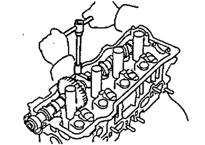
18. Remove the cylinder head cover.
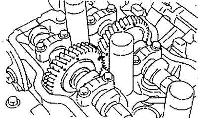
19. Remove the intake and exhaust camshafts.
Note: Since the camshaft end play is very small, it is necessary to keep the shaft in a horizontal position to prevent jamming and / or damage to the shaft when dismantling it, for this it is necessary to follow the dismantling procedure below.
A) Turn the camshaft 2-3 turns with a wrench, first turn the crankshaft so that the pistons are in the middle position. Apply paint marks to the crankshaft pulley for subsequent installation.
b) Find the alignment marks on the gears and mark them with a marker.
V) Install the camshafts in their original position and measure the thermal clearances in the valves in order to immediately adjust them during assembly.
A. Remove the exhaust camshaft.
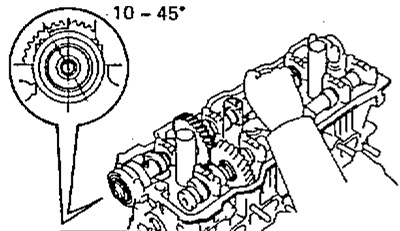
A) Install the intake camshaft so that the hole for the technological bolt of the intake camshaft gears is 10-45°before installation at TDC, as shown in the figure.
Note: In this position, the lobes on the exhaust camshafts of cylinders #2 and #4 act on the valve lifters.
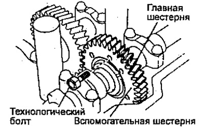
b) Attach the exhaust camshaft sub gear to the main gear with a service bolt.
Recommended process bolt:
- thread diameter - 6 mm
- thread pitch - 1.0 mm
- bolt length - 16-20 mm
Note: When removing the camshaft, make sure that this operation neutralizes the torsional force of the auxiliary gear plate washer.
V) Apply paint to the camshafts marks for their subsequent alignment during installation.
G) Evenly loosen and remove the bearing cap bolts in several passes in the following sequence: #5 - #1 - #2 - #4.
Note: do not loosen the #3 bearing cap bolts in this operation.
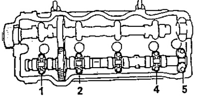
d) Remove bearing caps #1, #2, #4 and #5.
e) Loosen and remove the two #3 bearing cap bolts one by one.
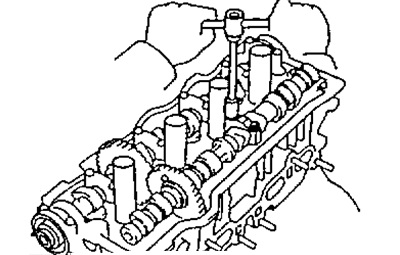
and) Remove bearing cap #3 and exhaust camshaft.
Note:
- - If the camshaft does not rise straight and horizontal, retighten the No. 3 bearing cap bolt and follow the steps to install the bearing caps and dowel pin. Then do the operations to remove the exhaust camshaft again.
- - Do not use a special tool to remove the camshaft.
Remove the intake camshaft.
A) Set the inlet camshaft locating pin at 80-115°until it is at TDC.
Note: In this position, the lobes on the intake camshafts of cylinders #1 and #3 act on the valve lifters.

b) Unscrew the two bolts, remove the front bearing cover and oil seal.
V) Evenly loosen and remove bearing cap bolts #2, #4 and #5 in several passes in the following sequence: #5 - #2 - #4.
Note: do not loosen the #3 bearing cap bolts in this operation.
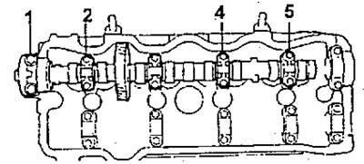
G) Remove bearing caps #2, #4 and #5.
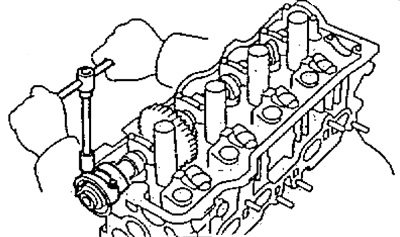
d) Loosen and remove the two #3 bearing cap bolts one by one.
e) Remove bearing cap #2 and camshaft.
Note:
- - If the camshaft does not rise straight and horizontal, retighten the #2 bearing cap bolts and follow the steps to install the bearing caps and dowel pin. Then do the operations to remove the exhaust camshaft again.
- - Do not use a special tool to remove the camshaft.
20. If necessary, disassemble the exhaust camshaft.
A) Install the camshaft in a vise as shown.
Note: Do not damage the camshaft as it is fragile.
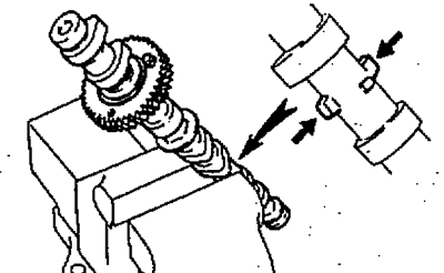
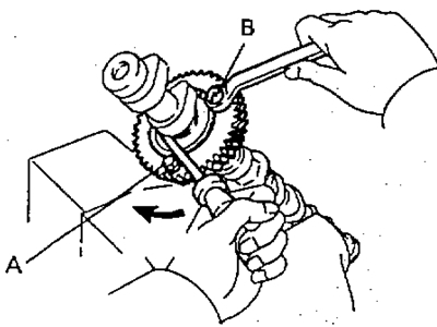
b) Insert process bolt (A) into the technological hole of the auxiliary gear of the camshaft drive,
V) Use a screwdriver to turn the auxiliary gear clockwise, and remove the technological bolt (IN).
Note: Be careful not to damage the camshaft.
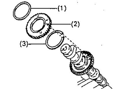
G) Remove the retaining ring with pliers.
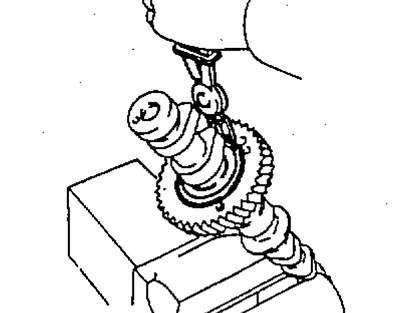
d) Remove:
- (1) spring washer;
- (2) Auxiliary camshaft drive gear;
- (3) Camshaft gear snap ring.
21. Remove the cylinder head
A) Evenly loosen and remove the 10 cylinder head bolts in several passes in the sequence shown in the figure.
Note: If the bolts are loosened incorrectly, the cylinder head may be deformed or cracked.
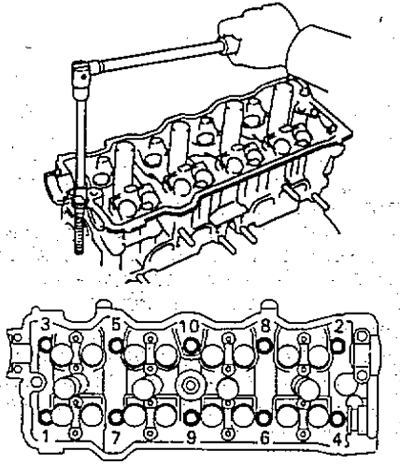
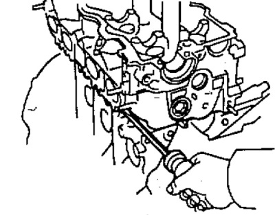
b) Remove the cylinder head from the guide pins on the cylinder block and lay it on a workbench with wooden blocks and rags.
Note: If the block head is difficult to remove, you can use a powerful screwdriver, inserting it into the gas joint, as shown in the figure. However, take care not to damage the surfaces of the head and block, as well as the head gasket.