



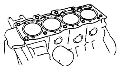
2. Install the cylinder head mounting bolts.
Note:
- - The cylinder head mounting bolts are tightened in two stages.
- - If any cylinder head mounting bolt is broken or deformed, replace it.
a) Apply a thin layer of engine oil to the threads and under the heads of the mounting bolts.
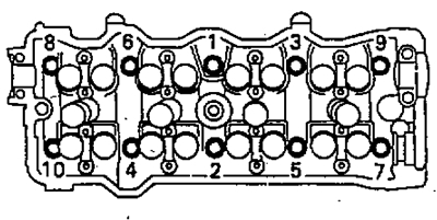
b) Install and tighten the 10 cylinder head bolts and plate washers evenly in several passes, in the sequence shown in the figure.
- Tightening torque - 49 Nm
If the specified tightening torque is not achieved when tightening any bolt, replace the bolt.
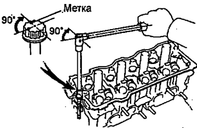
c) Apply paint marks to the front of the cylinder head bolts.

d) Tighten the cylinder head bolts 90° in the above sequence.
d) Check that the paint mark is at 90° from the original position.
2. Install the spark plug tubes (if you filmed).
a) Clean the spark plug tube holes in the cylinder head. Remove oil with kerosene or gasoline.
b) Apply sealant to the spark plug tube threads and install the tubes into the cylinder head.
c) Using the spark plug tube nut and a 30mm socket wrench, tighten the spark plug tubes.
- Tightening torque - 39 Nm
3. Assemble the exhaust camshaft (if you took it apart).
a) Place the camshaft in a vice.
Note: Be careful not to damage the camshaft.
b) Install the following parts:
- (1) Camshaft gear spring ring.
- (2) Auxiliary gear of the camshaft drive.
- (3) Spring washer.
Note: Align the guide pins on the gears with the ends of the spring.
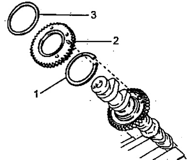
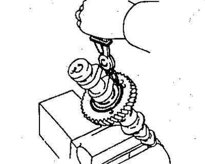
c) Using the tool, install the retaining rings.
d) Insert the technological bolt "A" into the technological hole of the auxiliary gear of the camshaft drive.
d) Using a screwdriver, align the hole of the camshaft drive main gear and the auxiliary gear by turning the auxiliary camshaft drive gear clockwise; then install the technological bolt (B).
Note: Do not damage the camshaft.
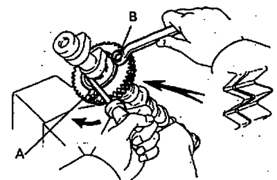
e) Align the teeth of the main and auxiliary gears and tighten the technological bolt B.
4. Install the camshafts.
Note: when installing the camshafts, it is necessary to take into account that the value of the axial clearance is very small, therefore the shafts must be placed in the bearing beds strictly horizontally, without distortions, in order to avoid jamming and/or damage to the shafts.
A. Install the intake camshaft.
a) Apply a layer of engine oil to the end bearing surfaces of the camshaft.
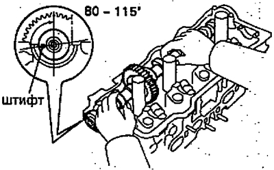
b) Set the intake camshaft to 80-115° until the piston of the first cylinder is at TDC.
Note: At these angles, the cam lobe projections of cylinders No.1 and No.3 of the intake camshaft press on the tappets.
c) Apply sealant to bearing cap #1 as shown.
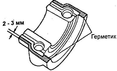
d) Install the bearing caps in accordance with the markings on their housings.
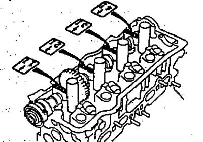
d) Apply a thin coat of engine oil to the threads and heads of the bearing cap bolts.
e) Install bearing cover No.3 and tighten its mounting bolts evenly in several passes.
- Tightening torque - 19 Nm
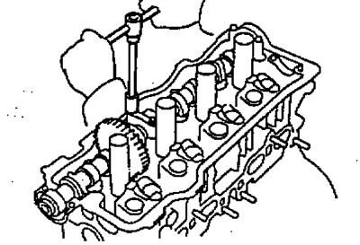
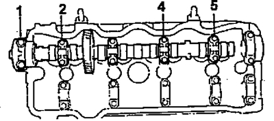
g) Install and tighten the bearing cap mounting bolts evenly in several passes, in the following sequence: No.4 - No.2 - No.5.
- Tightening torque - 19 Nm
h) Apply grease to the new seal.
i) Using a drift of suitable diameter and a hammer, install the seal
B. Install the exhaust camshaft.
a) Set the intake camshaft alignment pin to the 10-45 BTDC position.
Note: in this case, the projections of cams No.2 and No.4 of the cylinders of the intake valve camshaft press on the tappets.
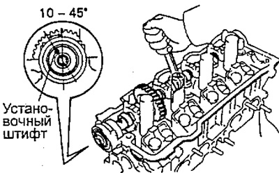
b) Apply a layer of engine oil to the end bearing surfaces of the camshaft.
c) Engage the gears of the exhaust and intake camshaft drives, aligning the timing marks on the gears with each other.
d) Keeping the gears engaged, roll the exhaust camshaft into the seats of its journals on the cylinder head.
Note: If there are also assembly marks on the gears as shown in the figure, do not use these marks for installation.
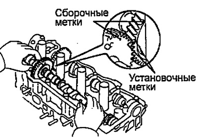
d) Turn the intake camshaft clockwise until the exhaust camshaft fits into the bearing journals without rolling.
Note: It is very important to follow the tightening sequence of the bearing cap bolts in the following steps.
e) Install the bearing caps.
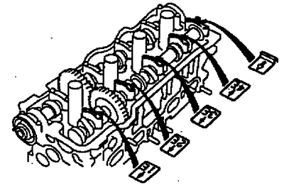
g) Apply a thin coat of engine oil to the threads and under the heads of the bearing cap bolts.
c) Install bearing cover No.3 and tighten its mounting bolts evenly in several passes.
- Tightening torque - 19 Nm
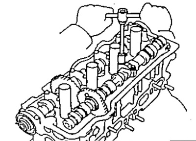
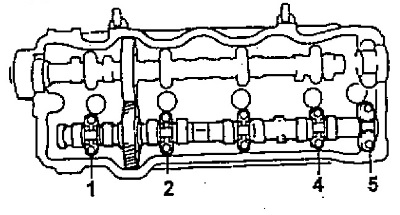
i) Install and tighten the bearing cap bolts evenly in several passes, in the following sequence: No.2 - No.4 - No.1 - No.5.
k) Unscrew the technological bolt "B".
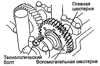
l) Turn the camshafts and check the alignment of the marks on the gears.
5. Turn the camshaft and position the cams with the working projections facing up, check and adjust, if necessary, the clearance in the valve drive.
6. Install segment plugs (if they were filmed).
a) Remove the old sealing material.
b) Apply sealant to the segment plugs as shown in the figure.
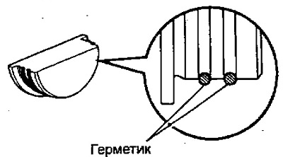
c) install two segment plugs into the cylinder head.
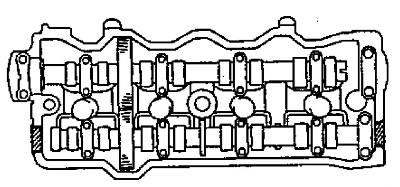
7. Install the cylinder head cover.
a) Remove any remaining old gasket.
b) Apply sealant to the cylinder head as shown in the figure.
Note: When using an old gasket, lubricate the entire surface.
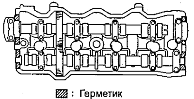
c) Install the gasket on the cylinder head cover.
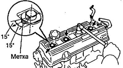
d) Install the cylinder head cover and spark plug tube seals with nuts. Tighten the nuts evenly in several passes.
- Tightening torque - 23 Nm
Note: Install the spark plug tube seals so that their marks are positioned as shown in the illustration.
Connect the exhaust pipe.
Tightening torque:
- exhaust manifold mount - 63 Nm
- fastening to the intermediate pipe of the exhaust system - 44 Nm
9. Install vacuum receiver stand No.2.
- Tightening torque - 44 Nm
10. Connect the coolant bypass tube.
- Tightening torque - 20 Nm
11. Connect the heater outlet hose.
12. Connect the coolant bypass hose.
13. Connect the fuel inlet hose and fuel return hose.
14. Connect the radiator inlet hose.
15. Install the generator assembly and the generator adjusting bar.
Tightening torque:
- bracket mount - 53 Nm
- fastening to the coolant pump - 22 Nm
16. Connect the wire harness.
17. Connect the vacuum hoses.
18. Install the accelerator cable bracket.
19. Connect the throttle valve control cable (automatic transmission).
20. Connect the accelerator cable.
21. Install the distributor (4S-FE) or combined ignition unit (3S-FE).
22. Install the timing belt (see section "Timing belt").
23. Fill the engine with coolant.
24. Disconnect the negative terminal from the battery.