Contents: Series A ↓ 3S-FE, 4S-FE ↓
Series A
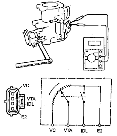
1. Check the throttle position sensor.
a) (4A-FE with automatic transmission) Apply vacuum to the throttle damper.

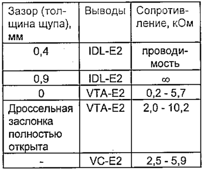
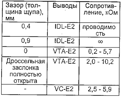
b) Insert a 0.4 or 0.9 mm thick flat feeler gauge between the throttle stop adjusting screw and the lever.
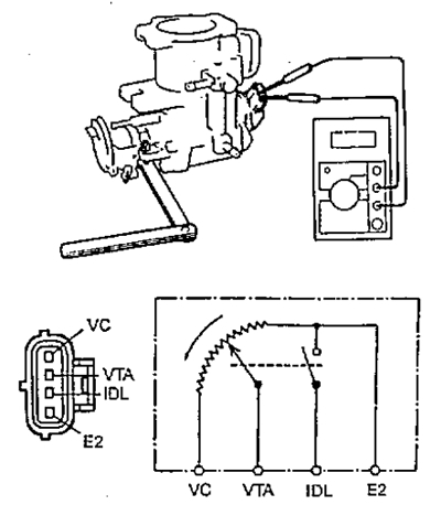
c) Using an ohmmeter, measure the resistance between the corresponding terminals of the sensor connector at different throttle positions.
3S-FE, 4S-FE
Except 4S-FE with manual transmission
1. Check the throttle position sensor.
a) Insert a 0.4 or 0.9 mm thick flat feeler gauge between the throttle stop adjusting screw and the lever.
b) Using an ohmmeter, measure the resistance between the corresponding terminals of the sensor connector at different throttle positions.
4S-FE with manual transmission
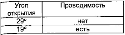
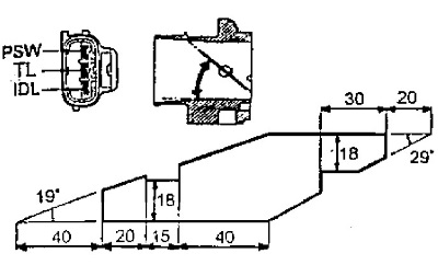
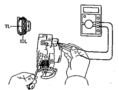
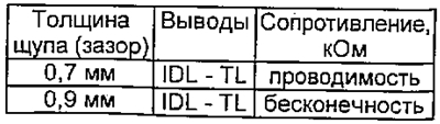
1. Check the continuity between the terminals of the throttle valve connector by installing a flat feeler gauge with a thickness of 0.70 and 0.90 mm between the adjusting screw and the throttle valve lever.
Make an angle template as shown in the figure and use it to set the throttle opening angle (19° or 29°). Measure the resistance between the "PSW" and "E2" terminals.