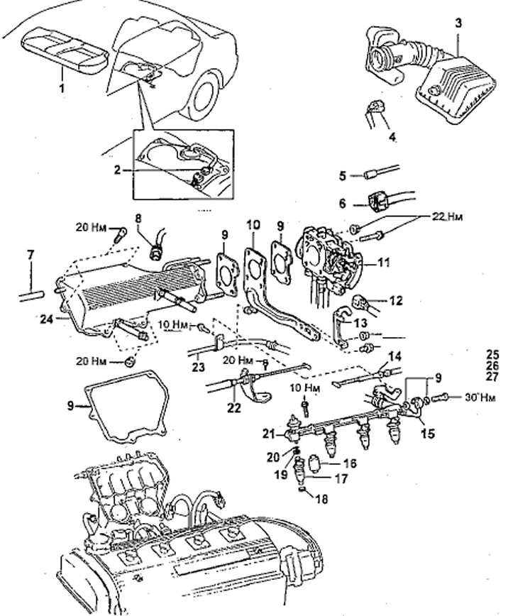
Removal and installation injectors (5A-FE)
1 - rear seat cushion,
2 - fuel pump connector,
3 - air filter cover with air duct,
4 - connector of the intake air temperature sensor,
5 - vacuum hose (fuel vapor accumulator),
6 - throttle position sensor connector,
7 - fuel pressure regulator vacuum hose,
8 - fuel vapor accumulator solenoid valve connector,
9 - gasket,
10 - intake manifold upper part stand,
11 - throttle body assembly,
12 - idle speed control system valve connector,
13 - engine lift bracket,
14 - throttle valve control cable,
15 - fuel hose,
16 - spacer,
17 - nozzle,
18 - insulator,
19 - safety sleeve,
20 - O-ring seal,
21 - fuel manifold,
22 - accelerator cable,
23 - fuel pipe,
24 - intake manifold upper cover.
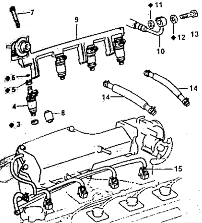
Removal and installation injectors (4A-FE, A-FE)
1 - fuel return pipe,
2 - fuel pressure regulator vacuum hose,
3 - injector insulator,
4 - nozzle,
5 - safety sleeve,
6 - O-ring seal
7 - fuel manifold mounting bolt (M3 = 9.3 Nm),
8 - check,
9 - fuel manifold,
10 - fuel inlet hose,
11 and 12 - gaskets,
13 - bypass bolt (M3 = 29 Nm),
14 - crankcase ventilation hoses,
15 - injector connector.
Removal injectors (4A-FE, 5A-FE, 7A-FE)
1. Disconnect the (-) cable from the negative battery terminal.
Note: For removal and installation details see above "Mechanical part of the engine".
2. Drain the coolant.
3. Disconnect the air filter hoses.
4. Disconnect the accelerator cable from the throttle actuator.
5. (Models with automatic transmission) Disconnect the throttle valve control cable from the throttle actuator.
6. Disconnect the idle speed control valve and throttle position sensor connectors.
7. (5A-FE) Remove the filter and air duct.
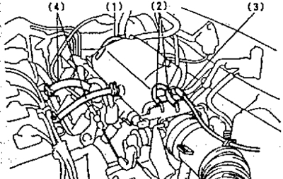
8. (5A-FE) Disconnect the hoses:
- (1) Fuel pressure vacuum hose,
- (2) fuel vapor accumulator solenoid valve vacuum hose,
- (3) fuel vapor canister vacuum hose,
- (4) two crankcase ventilation hoses.
6. Remove the throttle body.
7. Remove the engine lifting hook and upper intake manifold bracket.
a) Loosen the bolt(s) and remove the air tube and fuel hose.
b) After unscrewing the bolt and nut, remove the engine lifting hook and the upper intake manifold bracket with the gasket.
8. Remove the upper intake manifold cover.
a) Disconnect the 2 crankcase ventilation hoses.
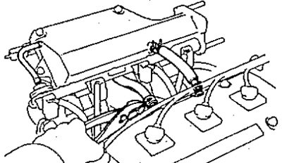
b) Disconnect the manifold absolute pressure sensor hose.
c) Using a 6 mm socket wrench, unscrew the 3 bolts and 2 nuts and remove the upper intake manifold cover together with the gasket.
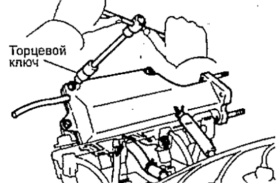
9. Disconnect the fuel return hose from the fuel pressure regulator.
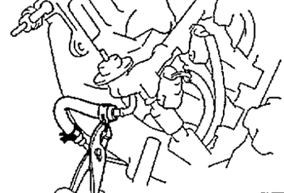
10. After unscrewing the bypass bolt with gaskets, disconnect the fuel supply pipe from the fuel manifold.

11. Disconnect the injector connectors.
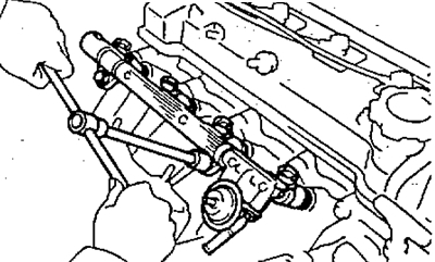
12. Remove the fuel manifold and injectors.
a) Unscrew 2 or 3 bolts and remove the fuel manifold together with the injectors.
Note: Be careful not to drop the injectors when removing the fuel rail.
b) Remove 4 insulators and 2 or 3 spacers from the cylinder head.
c) Remove the injectors from the fuel manifold.
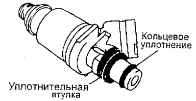
d) Remove the O-rings and protective sleeves from each injector.
Removal injectors (3S-FE, 4S-FE)
1. Disconnect the (-) cable from the negative battery terminal.
2. Remove the throttle body.
3. Remove the left engine lift bracket and intake manifold support No.2 by unscrewing the bolt and nut.
4. (Models with EGR system) Remove the EGR solenoid valve and tube.
a) Disconnect the vacuum hose (1) and the EGR hose (2) from the EGR valve.
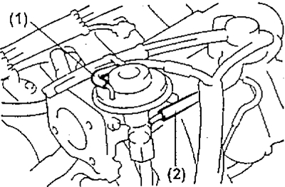
b) Loosen the EGR pipe nut on the cylinder head side.
c) Unscrew the 2 nuts and remove the EGR valve, the pipe assembly and the gasket.
5. Remove intake manifold bracket No.1 by unscrewing 2 bolts.
6. Remove the cylinder head cover.
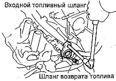
7. Disconnect the fuel inlet hose and fuel return hose.
a) Disconnect the engine wiring clamp from the wiring bracket,
b) Loosen the fuel pressure damper.
c) Remove the damper and 2 gaskets, disconnect the fuel inlet hose from the fuel manifold.
d) Disconnect the fuel return hose from the fuel return pipe.
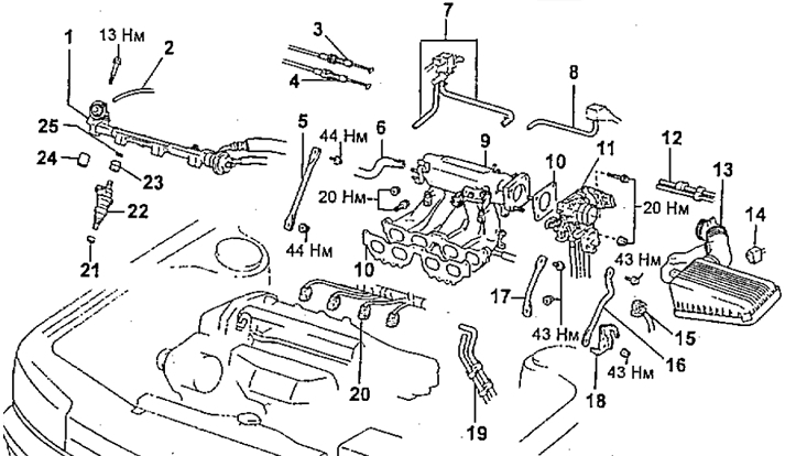
Removal and installation injectors (3S-FE, 4S-FE)
1 - fuel manifold,
2 - vacuum hose,
3 - throttle valve control cable (automatic transmission),
4 - accelerator cable,
5 - intake manifold stand No.2,
6 - brake booster vacuum hose,
7 - electro-pneumatic valve (air conditioning system),
8 - vacuum hose of the absolute pressure sensor in the intake manifold,
9 - intake manifold assembly,
10 - gasket,
11 - throttle body,
12 - fuel vapor accumulator vacuum hose,
13 - air filter cover with air duct,
14 - connector of the intake air temperature sensor,
15 - idle speed control system valve connector,
16 - bracket,
17 - intake manifold stand No.1,
18 - engine lifting hook,
19 - vacuum hoses (power steering system),
20 - injector connectors,
21 - insulator,
22 - nozzle,
23 - safety sleeve,
24 - spacer,
25 - O-ring seal.
8. Remove the fuel manifold and injectors.
a) Disconnect the 2 engine wiring clamps from the wiring brackets on the intake manifold.
b) Disconnect the vacuum hose from the fuel pressure regulator.
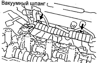
c) Disconnect the injector connectors.
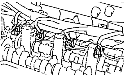
d) Unscrew the 2 bolts connecting the fuel manifold to the cylinder head.
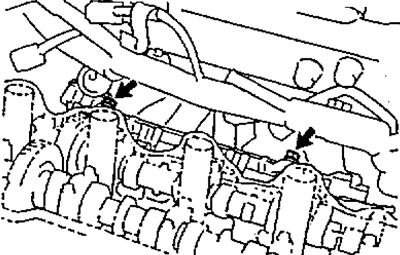
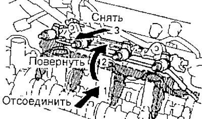
d) Remove the fuel manifold together with the injectors as shown in the figure.
Note: Handle the nozzles carefully and do not allow them to fall.
e) Remove four insulators and two spacers from the cylinder head.
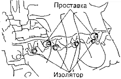
g) Remove the four injectors from the fuel manifold.
l) Remove the O-ring and sealing sleeve from each injector.