
Attention: When the battery is disconnected, all records in the computer's memory are erased.
For diagnostics, the following conditions must be met:
- The battery voltage must be at least 11 V.
- All extraneous electrical consumers must be turned off.
- Throttle must be fully closed (the throttle lever must rest against the stop screw).
- The gearbox must be in neutral.
- The engine must be at normal operating temperature. The temperature gauge should be in the middle position.
Fault reading
Put the ignition switch in position "ON". Do not start the engine.
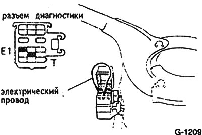
Jumper contacts E1 and T or T1 in the diagnostic connector. The diagnostic connector is located at the left suspension strut.
Read the DTC by flashing the diagnostic warning light on the front panel.
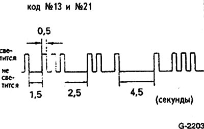
When a fault is indicated, the signal lamp flashes every 0.5 sec. The number of flashes corresponds to the fault code digit. After a break lasting 1.5 sec. the second part of the code is issued in the same way.
Attention: If there are several faults, their codes are issued in order, starting with the smallest one.
After issuing all the codes of the recorded faults, they are repeated at an interval of 4.5 seconds. until the jumper is removed from the connector between pins E1 and T.
Erasing a Recording
After the malfunction is eliminated, its code in the computer's memory must be erased.
Remove the cover from the fuse box under the 6-way trim on the driver's side.
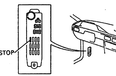
Take out for 15 seconds (at least) 15A fuse marked Stop and insert it again.
Attention: The higher the outside temperature, the longer the fuse must be removed.
Make a test drive and check if the warning light comes on. Otherwise, call the code from memory again.
Examination
The fault code indicates the section of the ignition or injection system where the fault should be looked for. A special catalog is required to accurately determine the fault. In addition, special measuring instruments are required for checks, which, as a rule, a motorist does not have. The following are some of the more general validation guidelines. A more thorough verification should be carried out in specialized workshops.
Note: If, for example, the code indicates a malfunction of the coolant temperature sensor, the malfunction may be in the control unit itself. The fault can be established either by replacing the sensor or by using special measuring instruments.
Disconnect the cable from the suspect node, check the connections for reliable contact. Clean contacts if necessary.
Check the attachment of the cable to the handpiece.
Check the resistance of the faulty element and compare it with the specified value.
Check the electrical wires of the control unit for an open.