
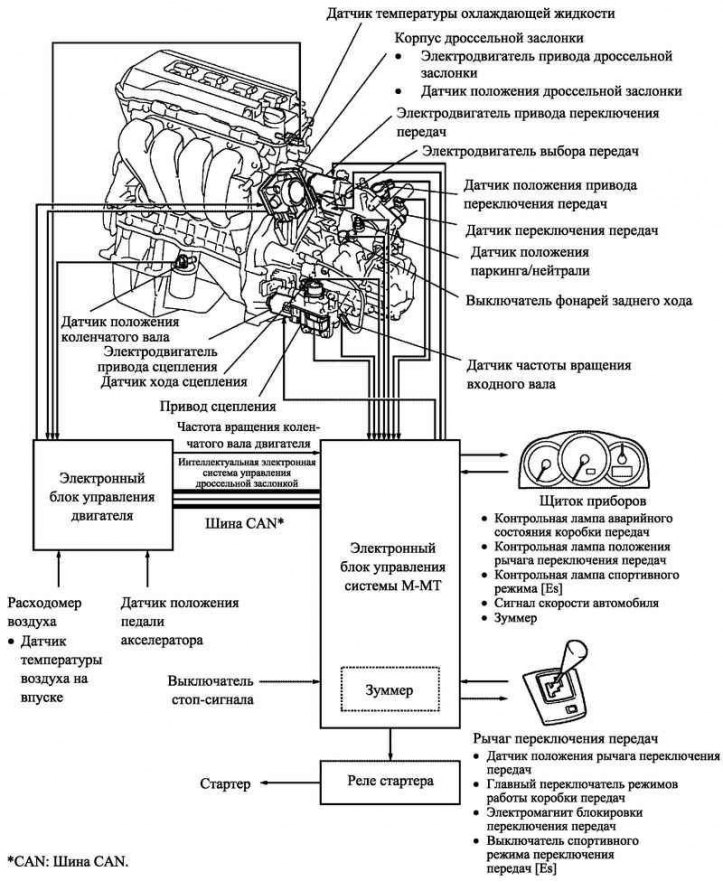
Pic. 3.59. Block diagram of the multimodal transmission system
In general, the device and principle of operation of the multimodal manual transmission installed on the new car model are similar to the units installed on Yaris / Echo cars.
This transmission has two shift modes: E mode, which shifts gears automatically depending on driving conditions, and M mode, which allows the driver to manually shift gears using the lever without using the clutch. In E mode, the driver can choose between two shift modes: Normal (E) and sports (Es) mode. E mode is more economical and easier to drive in this mode, while M mode is for those who prefer a sporty driving style.
The system consists of the following components: C251a multimodal manual transmission, ETCS-i (intelligent electronic throttle control system), ECU M-MT (electronic control unit for multimodal manual transmission), clutch with clutch basket with load control (LCC) and gear lever. The C251A multimodal manual gearbox is a modification of the C251 gearbox, additionally equipped with the following components: clutch drive, gear selection and shift mechanism drive, gearbox shaft speed sensor and park/neutral position sensor.
The device and principle of operation of the gear shift drive
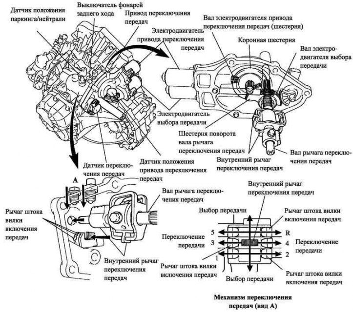
Pic. 3.60. The device and principle of operation of the gear shift drive
The shift actuator consists of the following components: drive motor, gear select motor, shift sensor, shift lever position sensor and shift mechanism (internal shift lever, shift lever shaft, shift motor gear, select motor shaft, ring gear and shift shaft turning gear). The drive cannot be disassembled.
The rotation of the shift motor shaft is transmitted through the gearbox to the shift lever shaft, as a result, the inner lever rotates.
The rotation of the shift motor shaft is converted by the rack and pinion into translational motion, resulting in movement of the shift lever shaft, as a result, the internal shift lever is displaced.
The movement of the inner shift lever is transmitted to the shift fork shaft through the shift shaft lever. This is how gear shifting works.
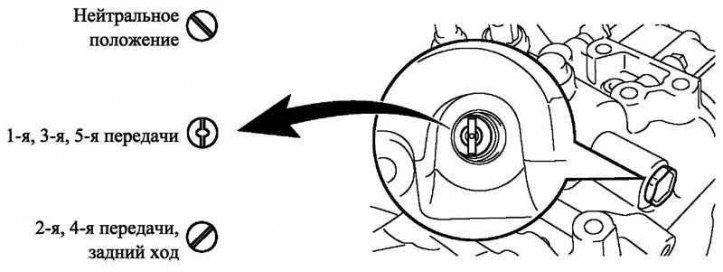
Pic. 3.61. Splined holes in the crankcase of the multimodal gearbox
Maintenance recommendation
Before removing the shift actuator, shift the gearbox to neutral. If it is not possible to engage the neutral gear due to a malfunction of the drive and (or) gearbox, unscrew the plug from the hole in the crankcase. Looking into the hole, you can see the slot on the end surface of the shaft. If necessary, insert a screwdriver into the slot and turn the shaft, placing the gearbox in neutral.
Gear selection and shift sensors
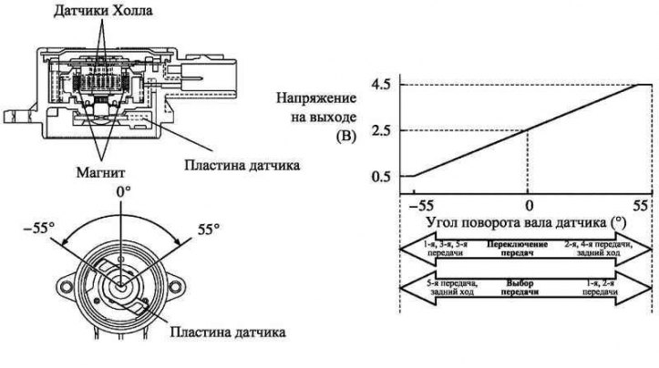
Pic. 3.62. Gear selection and shift sensors
The select and shift sensors include two Hall effect sensors and a magnet that rotates with the shift lever shaft. Sensors convert magnetic flux changes caused by the rotation of the select and shift motors (as a result - by turning the magnet), into an electrical signal that is transmitted to the electronic control unit of the gearbox. The electronic control unit of the gearbox uses this signal to evaluate the magnitude of the angular and axial stroke of the shaft (shifting and gear selection), determining by them the currently enabled transmission.
Engagement and gear selection sensors have the same output characteristics of the main and auxiliary circuits.