
General information
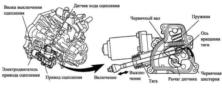
Pic. 3.63. clutch drive
The clutch drive consists of the following components: electric motor, clutch travel sensor, worm shaft, worm gear, rod, spring. The drive cannot be disassembled.
The rotation of the clutch motor shaft is transmitted to the worm pair, the worm gear rotates. A linkage attached to the worm gear moves the clutch release fork.
The spring acting on the worm wheel creates the force necessary for the thrust to reverse. The use of this spring reduces the load on the electric motor when the clutch is disengaged.
Clutch travel sensor
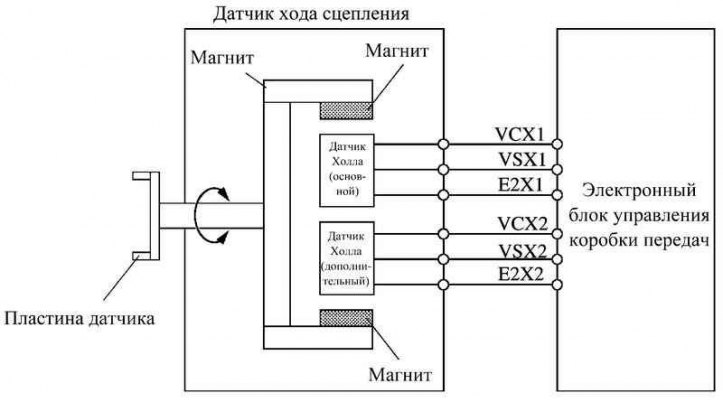
Pic. 3.64. Clutch Stroke Sensor Block Diagram
Like the gear select and shift sensors, the clutch travel sensor consists of two Hall effect sensors (main and additional) and a magnet turning with the drive worm gear.
Hall sensors convert changes in magnetic flux caused by the rotation of the clutch motor (as a result - by turning the magnet), into an electrical signal transmitted to the electronic control unit of the gearbox. The electronic control unit of the gearbox uses this signal to evaluate the amount of clutch travel.
The output characteristics of the main and auxiliary circuits of the clutch travel sensor are the same.
The clutch travel sensor is similar in design and principle of operation to gear selection and shift sensors.
Clutch basket with load control (LCC)
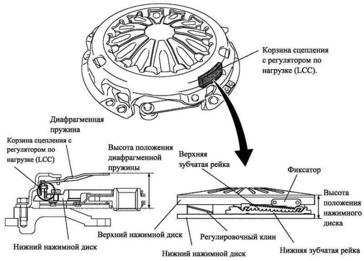
Pic. 3.65. Clutch basket with load control (LCC)
Clutch basket with load control (LCC) regulates the position of the pressure plate, preventing an increase in the workload on the drive due to wear on the surface of the driven disk.
Clutch basket with load control (LCC) is located in the clutch basket and consists of the following parts: a latch fixed to the upper pressure plate, a lower gear rack, an upper gear rack, an adjusting wedge and a spring mounted on the lower pressure plate.
With increasing workload in the clutch drive (determined by the current strength in the drive motor circuit) the electronic control unit of the gearbox drives the clutch actuator, moving the diaphragm spring into the operating range of the clutch basket with load control (LCC). This allows the clutch basket with load control (LCC) adjust the position of the pressure plate.
Principle of operation
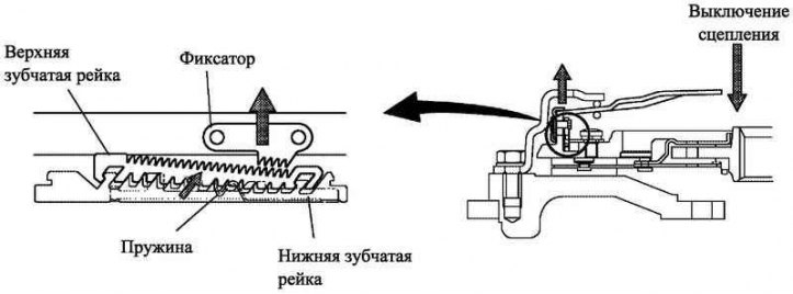
Pic. 3.66. The principle of operation of the clutch with a load regulator
When an increase in workload is detected in the clutch actuator (determined by the increase in current strength in the motor circuit) shortly after the vehicle is stopped and the engine is switched off, the transmission's electronic control unit regulates the clutch, thereby increasing the drive travel*. As a result of adjustment, the diaphragm spring is subjected to greater compression (operating range of the clutch basket with load control (LCC)), the upper pressure plate with the detent moves upwards to a greater height than usual. The latch then disengages from the upper toothed rack.
*The process is carried out before the clutch is engaged in the parking position, performed after the engine is turned off.
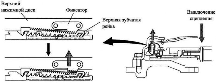
Pic. 3.67. Clutch operation with a load regulator when disengaging the latch and the upper gear rack
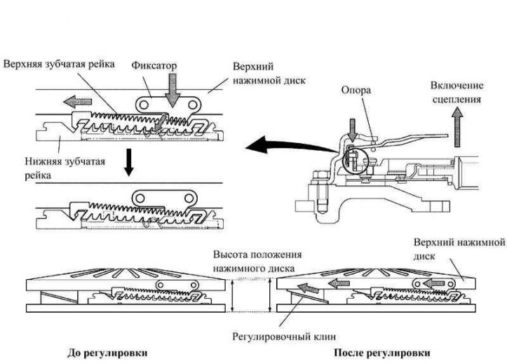
Pic. 3.68. Diaphragm spring height before and after clutch adjustment
After the release of the latch and the upper gear rack, the spring force shifts the upper gear rack along the teeth of the lower gear rack (diagonally right). As a result, the retainer and the upper gear rack are shifted by 1 tooth relative to the lower gear rack.
After that, the electronic control unit of the gearbox engages the clutch. In connection with the movement of the latch by 1 tooth relative to the lower gear rack, the latch, together with the upper pressure plate, moves to the left and engages with the lower gear rack.
The upper pressure plate, moving to the left, shifts up the surface of the adjusting wedge. The height of the position of the upper pressure plate increases. Due to the displacement of the upper pressure plate upwards, the height of the spring relative to the support decreases. As a result, the diaphragm spring is set to a lower height than before adjustment by the clutch basket with load control (LCC).