
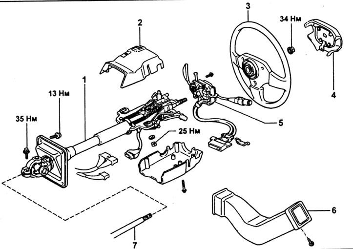
Steering column assembly. 1 - steering column, 2 - upper steering column pad, 3 - steering wheel, 4 - horn pad,_ 5 - combination switch, 6 - air duct, 7 - intermediate shaft.
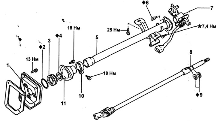
Steering column (option without angle adjustment). 1 - steering column hatch cover, 2 - o-ring, 3 - lower bearing, 4 - retaining ring, 5 - steering column tube, 6 - shear bolt, 7 - ignition lock bracket, 8 - main shaft, 9 - retaining ring, 10 - collar, 11 - bottom bracket.
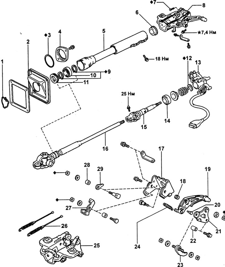
Steering column (angle adjustable option). 1 - retaining ring, 2 - steering column hatch cover, 3 - o-ring, 4 - steering column tube holder, 5 - steering column tube, 6 - bushing, 7 - shear head bolt, 8 - steering column mounting bracket, 9 - retaining ring, 10 - lower bearing, 11 - boot, 12 - retaining ring, 13 - ignition lock bracket, 14 - upper bearing, 15 - main shaft, 16 - countershaft, 17 - angle adjustment bracket, 18 - sleeve #1,19 - adjustment lever, 20 - pin, 21 - adjustment lever mounting bracket, 22 - bushing, 23 - pawl, 24 - tension spring, 25 - steering column mounting bracket, 26 - tension spring with cable, 27 - bracket stopper, 28 - sleeve No. 2, 29 - lever stroke limiter.
Removing
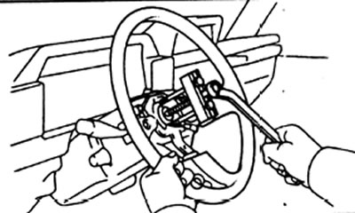
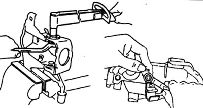
1. Removing the steering wheel.
A) Remove the signal cover and unscrew the nut.
b) Put alignment marks on the steering wheel and main shaft assembly.
V) Using a puller, remove the steering wheel.
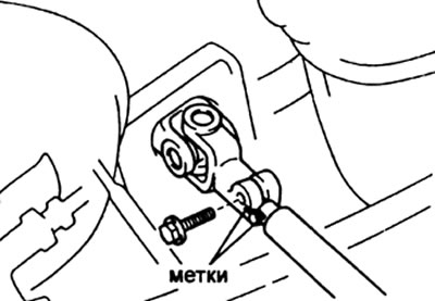
2. Removing the lower cardan joint,
A) Put alignment marks on the intermediate shaft and universal joint yoke.
b) Separate the universal joint and intermediate shaft.
Disassembly
Note: for the version without tilt adjustment, the removal of the corresponding parts is carried out in the same way.
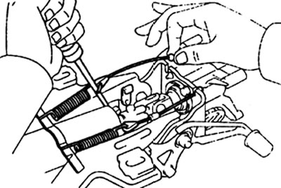
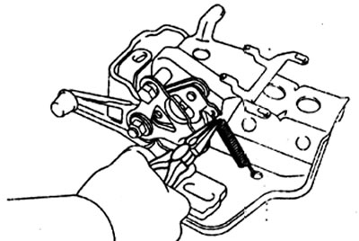
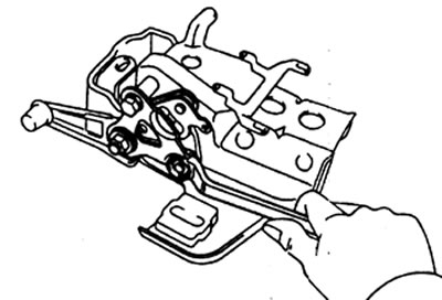
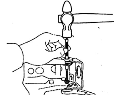
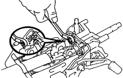
1. Removing the tension springs and cables.
A) Fully tilt the main shaft.
b) Using a screwdriver, remove the spring and cable.
2. Removing the intermediate shaft.
A) Put alignment marks on the intermediate shaft and universal joint yoke.
b) Loosen the bolt securing the intermediate shaft to the cardan joint.
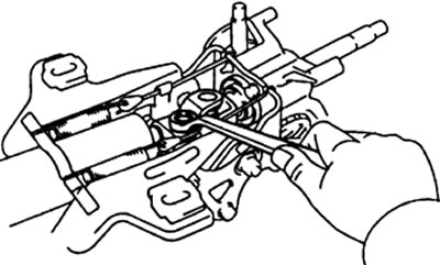
V) Remove the snap ring.
G) Disconnect the intermediate shaft from the main shaft.
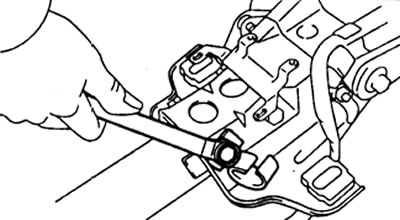
3. Turn away bolts and remove a pipe of fastening of a steering column from an arm of fastening of a steering column.
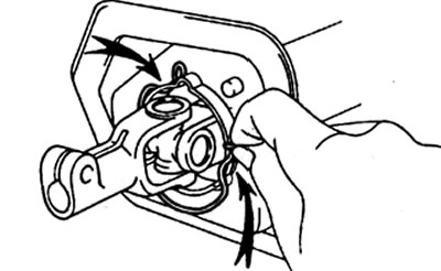
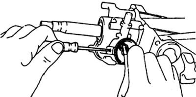
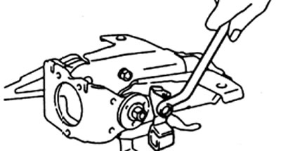
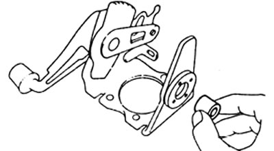
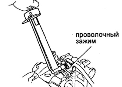
4. Removing the ignition lock cylinder.
A) Set the ignition key to position "ACC".
b) Press the latch with a thin rod and remove the ignition lock cylinder.
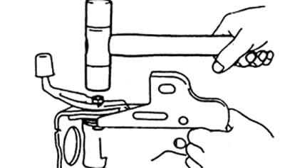
5. Removing the ignition lock bracket and main shaft.
A) Turn away two bolts and remove a stiffening element.
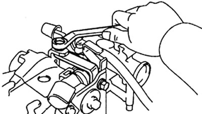
b) Use a chisel and hammer to loosen the shear bolt.
V) Turn away three bolts and disconnect an arm of the lock of the ignition from an arm of fastening of a steering column.
6. Remove the ignition switch.
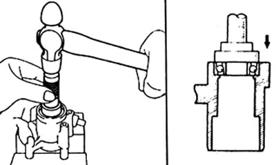
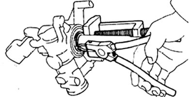
7. Removing the main shaft from the ignition lock bracket.
A) Using the special tool, compress the main shaft and the ignition lock bracket.
b) Using pliers, remove the retaining ring.

V) Loosen the special tool and remove the main shaft, spring and bushing from the ignition lock bracket.
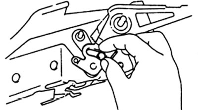
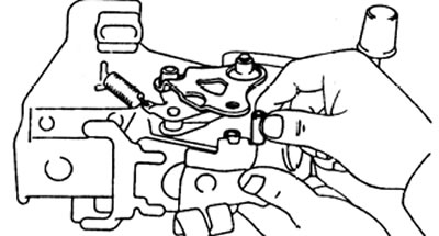
8. Removing the tilt angle adjustment bracket from the steering column mounting bracket.
A) Remove tension spring.
b) Turn away two nuts and a bolt, remove an arm of fastening of the lever of adjustment and take the plug.
V) Remove pin
G) Take off the doggy
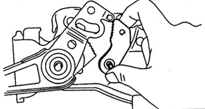
d) Loosen the dog bolt.
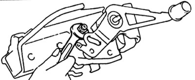
d) Turn away a nut and remove a bolt with a stopper of an arm.
e) Loosen the nut securing the angle adjustment lever.
and) Temporarily screw a flat nut onto the bolt and tap it with a plastic mallet.
h) Remove the nut, then remove the bushing and lever travel stop.
And) Loosen the mounting bolt, remove the nut and bushing.
Examination
1. Replacing the bearing in the ignition lock bracket (if necessary).
A) Using the special tool and a hammer, remove the bearing.
b) Apply grease to the bearing.
V) Using the special tool and a hammer, press the bearing into the ignition lock bracket.
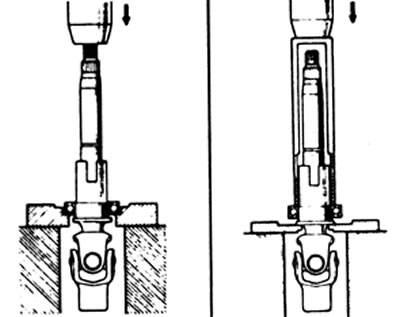
2. If necessary, replace the lower bearing.
A) Using the special tool and a press, remove the lower bearing from the main shaft.
b) Apply grease to the bearing.
V) Using the special tool and a press, press the lower bearing onto the main shaft.
3. If necessary, replace the intermediate shaft bearing.
A) Using pliers, remove the retaining ring.
b) Remove the bearing from the intermediate shaft.
V) Press in new bearing.
G) Using pliers, install the retaining ring.
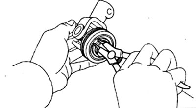
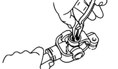
4. Replacement of the cross (if necessary).
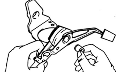
A) Remove the four retaining rings.
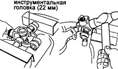
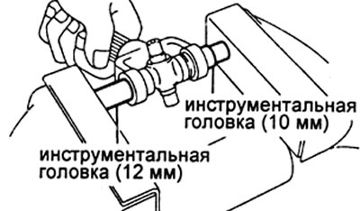
b) Using tool heads (12 and 22 mm) and a vise, press the bearing out of the joint cross.
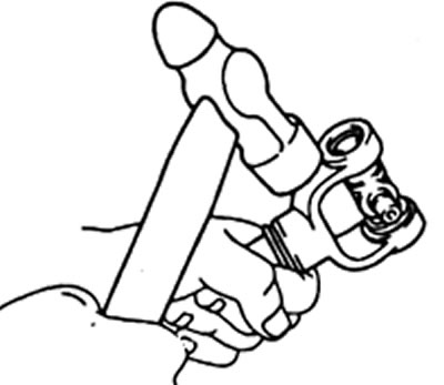
V) Clamp the bearing in a vise and with light blows of the hammer separate it from the cross.
Note: Removal of other bearings is carried out in the same way.
G) Apply lithium-based grease with molybdenum disulphide to bearings and spider.
Caution: Do not apply too much lubricant.
d) Using tool head (12 mm) and vise, press in the bearing.
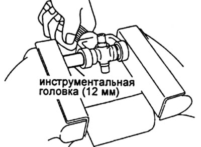
e) Using tool head (10 and 12 mm) and vise, adjust the position of the bearings so that the distance from each bearing to the edge of the fork is as large as possible and the same.
and) Select two circlips of the same thickness so that the end play is between 0.00 and 0.05 mm.
Attention: Do not reuse retaining rings.
| Label | Thickness, mm |
| No label | 1,175- 1,225 |
| Brown | 1,225- 1,275 |
| Blue | 1,275- 1,325 |
Assembly
1. Apply grease to the friction surfaces of the parts.
2. Install the pawl mounting bolt.
Tightening torque - 18 N.m
3. Installing the adjustment lever on the bracket.
A) Select bushing No. 1 according to the table to eliminate the play.
b) Install the adjustment lever and sleeve #1 onto the bracket.
V) Select sleeve #2 from the table to eliminate backlash.
G) Install sleeve #2 into the bracket.
d) Drive the special bolt into the angle adjustment bracket.
e) Install doggy.
and) Install the extension spring and pin.
h) Install the bushing and adjustment arm mounting bracket.
Tightening torque - 18 N.m
4. Installing the lever stroke limiter,
A) Using the table below, select the lever travel stop.
| Label | Thickness, mm |
| No label | 0,197-0,203 |
| 5 | 0.495 - 0,505 |
| 8 | 0,795 - 0,805 |
| 14 | 1,395- 1,405 |
| 18 | 1,795-1,805 |
b) Install the lever travel stop, bolt, washer and locknut.
Tightening torque - 18 N.m
5. Installing the bracket stopper bolt.
A) Install the stopper bolt, bracket stopper, washer, and tighten the locknut as shown.
b) Tighten the nut while holding the bracket stop as shown.
Tightening torque - 10 N.m
6. Assembly of the main shaft and ignition lock bracket.
A) Assemble the bushing, spring and main shaft, and insert into the ignition lock bracket.
b) Using the special tool, compress the main shaft with the bracket and install the circlip.
Note: Do not overtighten the special tool.
7. Assembly of tilt angle bracket and ignition lock bracket.
A) Apply sealant to one or two bolt threads.
Sealant: Three Bond 1324 or equivalent.
Note: This sealant will not air dry. Apply hardener only when the sealant is evenly, without cavities, applied to the bolt threads.
b) Install two mounting bolts (one of the bolts with the wiring clamp).
Tightening torque - 7.4 N.m
V) Install the shear head bolt and tighten until the head is sheared.
G) Install the stiffener and tighten the two mounting bolts.
8. Establish an arm of fastening of a steering column on a pipe of a column.
Tightening torque - 18 N.m
9. Install the retainer and new O-ring on the steering column tube and then install the steering column hatch cover.
10. Installation of the intermediate shaft.
A) Align the alignment marks on the mainshaft yoke and intermediate shaft, and tighten the mounting bolt.
Tightening torque - 25 N.m
Note: Be careful not to pop out the oil seal when installing the intermediate shaft.
b) Secure the steering column tube with the circlip.
11. Install extension springs and cables.
12. Checking the operation of the lever and angle adjustment bracket.
A) Make sure the end of the main shaft is not subject to play.
b) Make sure the main shaft is secure in all six positions.
13. Installing the ignition lock.
A) Set the ignition key to position "ACC", then install the ignition lock cylinder to the ignition lock bracket.
6) Install the ignition switch.