
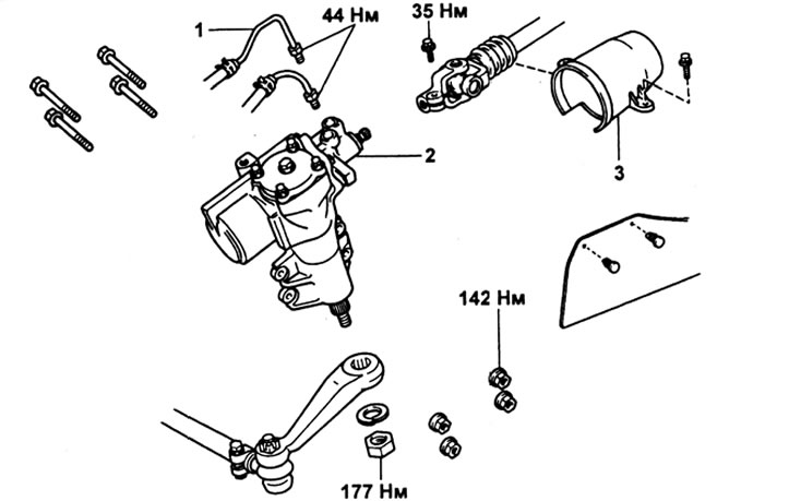
Steering gear. 1 - pressure and return pipelines; 2 - steering mechanism; 3 - hinge cover.
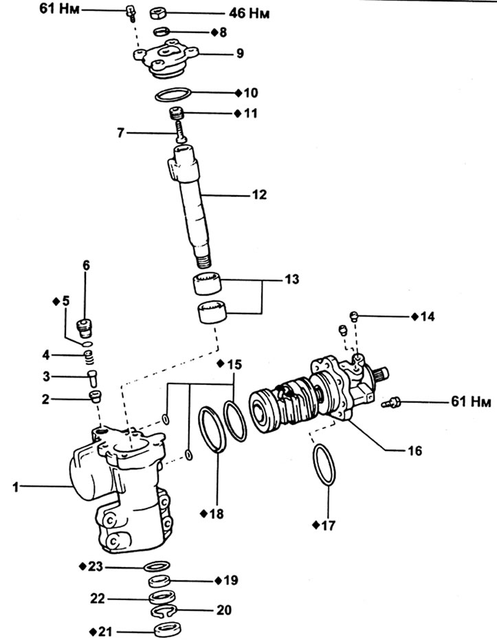
Steering gear. 1 - body; 2 - plunger; 3 - plunger guide; 4 - spring; 5 - sealing ring; 6 - plunger guide nut; 7 - adjusting screw; 8 - washer; 9 - end cap; 10 - sealing ring; 11 - locknut; 12 - steering arm shaft; 13 - needle bearing; 14 - fitting seat; 15 - sealing ring; 16 - control valve assembly; 17 - sealing ring; 18 - fluoroplastic ring; 19 - fluoroplastic ring; 20 - retaining ring; 21 - stuffing box; 22 - spacer; 23 - sealing ring.
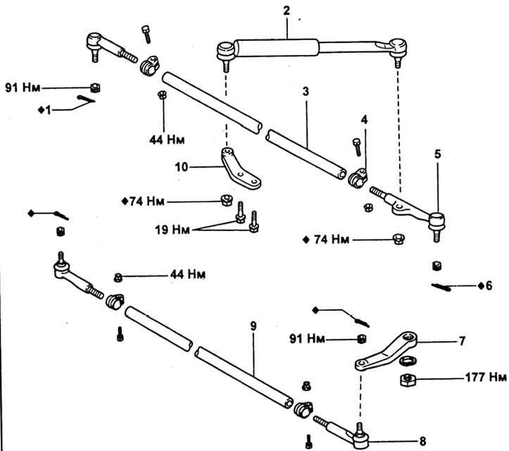
Steering gear. 1 - cotter pin; 2 - damper; 3 - transverse thrust; 4 - clamp; 5 - tip of the transverse thrust; 6 • cotter pin; 7 - steering arm; 8 - tip of the transfer rod; 9 - gear rod; 10 - damper cheek.
Removal and installation
1. Detaching the steering arm.
A) Loosen the steering knuckle nut.
b) Using a puller, disconnect the steering arm from the shaft.
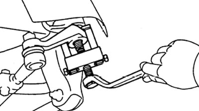
V) Remove the nut, spring washer and steering arm.
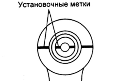
Note: When attaching the pitman arm, align the alignment marks on the pitman arm and armpit shaft, then install the spring washer and tighten the nut.
The tightening torque of the nut is 177 Nm.
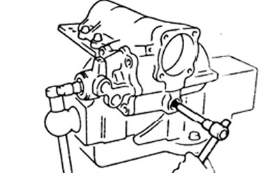
2. Detaching the lower universal joint from the steering gear.
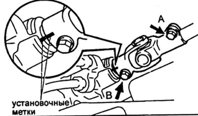
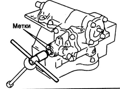
A) Put alignment marks on the worm shaft and universal joint yoke.
b) Loosen the top bolt "A" cardan joint.
V) Loosen the bottom bolt "B* hinge.
G) Slide the hinge back to disengage it from the screw shank.
Disassembly
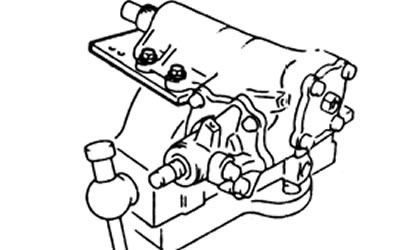
1. Attach the steering gear to the special tool and clamp the tool in a vise.
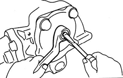
2. Loosen the adjusting screw locknut. Remove four bolts. Screw in the adjusting screw until the end cap separates and comes out of the housing.
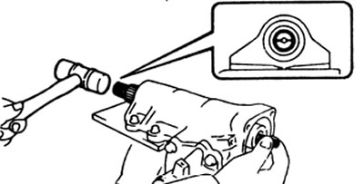
3. Use a plastic mallet to tap on the end of the bipod shaft, and remove the shaft.
4. Using the special tool, remove the plug guide nut. Remove the spring, plunger and plunger guide. Remove the sealing ring.
5. Removing the control valve assembly,
A) Loosen the four body screws.
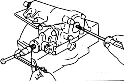
b) Using the special wrench, turn the propeller shaft clockwise to disengage the control valve assembly from the steering gear housing.
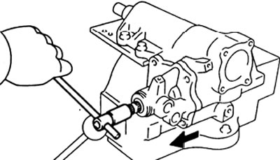
V) While holding the ball screw from moving, remove the control valve body and ball screw.
Attention: do not allow the -nut-rail to be removed from the propeller shaft.
G) Remove the sealing ring.
Examination
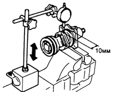
1. Checking the clearance of the ball screw.
A) Secure the control valve body in a vise.
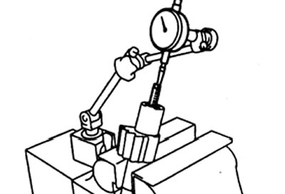
b) Using an indicator, measure the clearance in the ball screw while the piston is moving (rail nuts) up and down.
Maximum clearance - 0.15 mm
V) If the clearance is greater than the limit, replace the control valve assembly.
2. Checking the axial clearance of the adjusting screw.
A) Clamp the steering arm shaft in a vise.
b) Using an indicator, measure the axial clearance of the adjusting screw. If the gap is more than the maximum allowable, then adjust it.
Maximum clearance - 0.03 - 0.05 mm
3. Adjusting the axial clearance of the adjusting screw (if it is needed).
A) Use a chisel and hammer to remove the caulk from the locknut, then loosen the locknut.
b) Adjust the screw until the correct clearance is obtained.
V) Install and tighten the new locknut, then caulk the locknut.
Assembly
1. Installing the control valve assembly.
A) Install the O-rings to the steering gear housing and to the control valve housing.
b) Mount the steering gear housing on the special tool and clamp the special tool in a vise.
V) Insert the control valve assembly into the steering gear housing as shown.
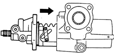
G) Tighten the mounting bolts.
Tightening torque - 46 N.m
Attention: do not damage the PTFE ring.
d) Using a torque wrench and adapter, check the ball screw preload.
Preload - 0.3 - 0.5 N.m
Note: keep the ball screw from turning.
e) If the preload is not correct, replace the ball screw assembly.
2. Install the plunger, plunger guide, and spring. Install a new O-ring on the guide nut and tighten the nut.
Tightening torque - 20 N.m
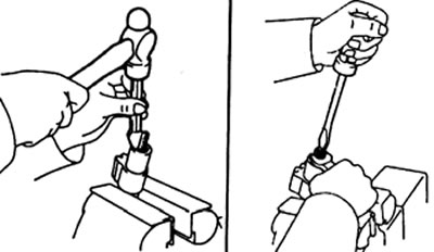
3. Installation of the steering arm shaft.
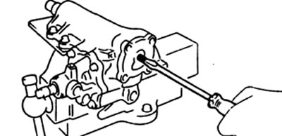
A) Install a new o-ring on the end cap. Using a screwdriver, assemble the pitman shaft and end cap.
Note: Loosen the adjusting screw completely.
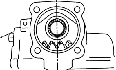
b) Install the ball screw in the center of the steering gear. Insert the bipod shaft so that the middle teeth engage with the piston teeth.
V) Install the four bolts and tighten the bolts crosswise.
Tightening torque - 46 N.m
4. Determination of the central position of the steering mechanism.
A) Using the adapter, turn the steering gear screw shank from lock to lock and determine the center position.
b) Mark the screw shank and body to indicate the center position.
5. Checking the total preload.
A) Install the torque wrench with adapter on the screw shank.
b) Turn the adjusting screw while measuring the preload.
Total preload - 0.74 - 0.96 N.m
6. Install a new washer.
7. Install and tighten the screw locknut while holding the adjusting screw.
Tightening torque - 46 N.m
8. Check the total preload.