Anchor check
1. Using an ohmmeter, check for continuity between the collector fins. Otherwise, replace the anchor.
2. Check if there is a short circuit in the armature winding on "mass".
Using an ohmmeter, check that there is no continuity between the collector fins and the armature core. Otherwise, replace the anchor.
Manifold check
1. Inspect the working surfaces of the collector lamellas, if they are dirty and burnt, clean the working surfaces with sandpaper No. 400 or grind the collector on a lathe.
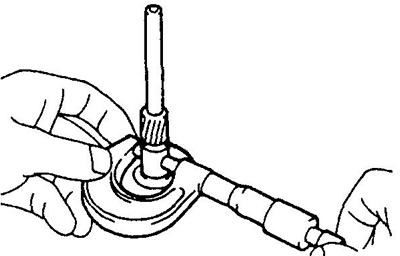
2. Mount the anchor on the prisms and measure the runout of the collector.
The maximum allowable radial runout of the collector:
- type 1 - 0.40 mm
- type 2 - 0.05 mm
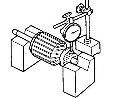
If the runout exceeds the specified value, then machine the manifold on a lathe.
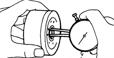
3. Using a caliper, measure the manifold diameter.
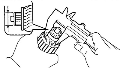
- Nominal collector diameter - 28 mm
- The minimum allowable collector diameter is 27 mm
If the collector diameter is less than the minimum allowable, then replace the starter armature.
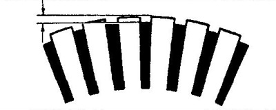
4. Make sure that the grooves between the collector lamellas are free of dirt and foreign particles.
- The nominal value of the protrusion of the collector lamellas is 0.6 mm
- The minimum allowable protrusion of the lamellas is 0.2 mm
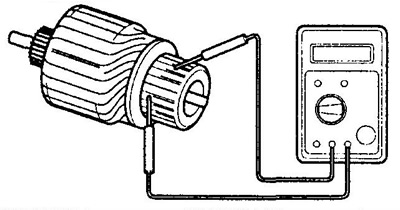
Stator check
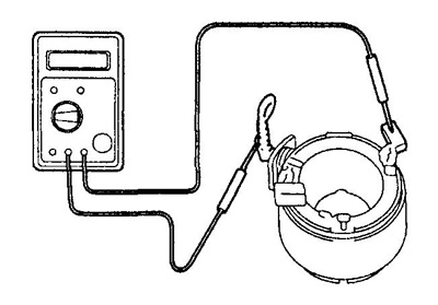
1. Using an ohmmeter, check for continuity between the wires (brushes).
- type 1 - 4 wires
- type 2 - 2 wires
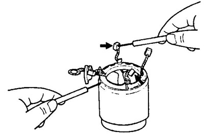
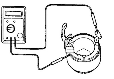
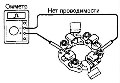
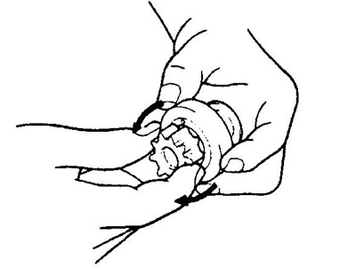
2. (Type 1) Check for continuity between field side brush and ground (stator), as it shown on the picture.
If there is no continuity, replace the stator.
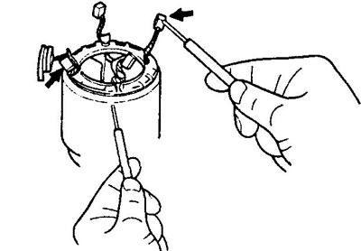
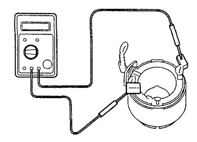
3. (Type 1) Make sure there is no continuity between the field winding and ground (stator), as it shown on the picture.
If there is no continuity, replace the stator.
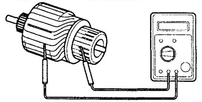
4. (Type 2) Check for continuity between brush and stator housing.
5. (Type 2) Check for continuity between the brushes.
6. (Type 2) Check for continuity between brushes and terminal "WITH".
Checking the brushes
Using a caliper, measure the height of the brushes.
Nominal brush height:
- type 1 - 10.0 mm
- type 2 - 14.0 mm
Minimum allowable brush height:
- type 1 - 6 m
- type 2 - 9 mm
If the brush height is less than the minimum allowable value, replace the brushes and touch up with sandpaper.
Checking the brush holder
Check brush holder insulation. Using an ohmmeter, check that there is no continuity between the positive and negative brush holders. Otherwise, replace the brush holder.
Checking brush springs
Use the steelyard to measure the tension of the brush springs at the moment of their separation from the brush.
- Nominal force of brush springs - 14-18 N
- The minimum force of the brush springs is 9 N
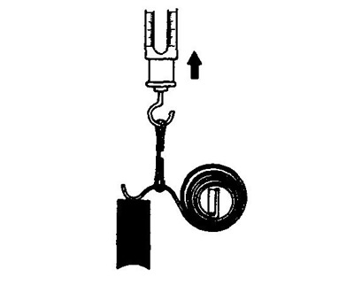
If the spring force is less than the minimum value, replace the brush springs.
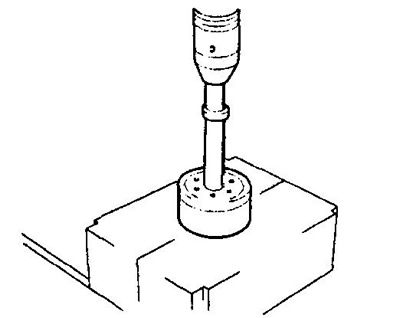
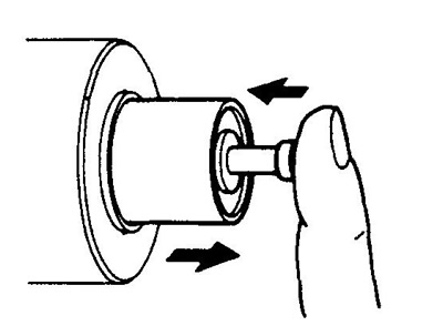
Replacing drive side cover bearing
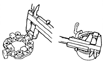
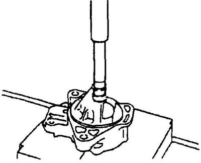
1. Using the special tool, press out the bearing.
2. Press in the new bearing.
Check carrier and bearings (type 2)
1. Check carrier and bearings.
A) Using a micrometer, measure the outside diameter of the bearing carrier seat.
- Nominal diameter - 14.980 - 15.000 mm
b) Measure the inside diameter of the bearing.
V) Calculate the clearance between the bearing and carrier by subtracting the diameter of the carrier shaft from the inside diameter of the bearing.
Gap:
- nominal - 0.03 mm
- maximum - 0.10 mm
If the clearance exceeds the maximum value, replace the carrier and bearing.
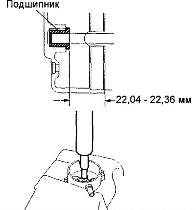
2. If necessary, replace the bearing.
A) Remove the bearing using a puller.
b) Using a press and a mandrel, press in the new bearing.
Note: the bearing must be pressed in so that its edge does not reach the edge of the central bearing by 0.05 mm.
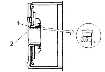
1 - central bearing,
2 - bearing.
3. Check up a backlash of satellites.
A) Measure the inner diameter "A" satellite holes.
b) Measure the diameter of the satellite shaft.
V) Calculate clearance.
- Nominal clearance - 0.03 mm
- Limit clearance - 0.10 mm
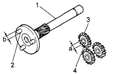
1 - carrier,
2 - satellite axis,
3 - satellite,
4 - bushing.
Checking and replacing the starter cover bearing
1. Measure the inside diameter of the bearing.
2. Measure the diameter of the armature shaft.
- Nominal diameter - 7 mm
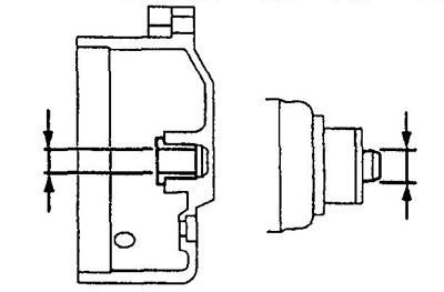
3. Calculate the clearance between the shaft and the bearing.
- Nominal clearance - 0.03 mm
- Limit clearance - 0.10 mm
4. If necessary, replace the bearing.
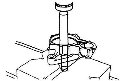
A) Using the special tool, remove the bearing as shown in the figure.
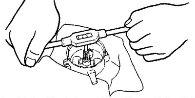
b) Press in new bearing.
Checking the freewheel and gears
1. Inspect the tooth surfaces for excessive wear or chipping.
Replace gears if worn or damaged.
If there are scores or chips on the surfaces of the freewheel gear teeth, check the running surfaces of the teeth of the flywheel ring gear.
2. Check freewheel.
Make sure the drive gear rotates freely in one direction and does not rotate in the other direction.
If conditions are not met, replace freewheel.
Checking the traction relay
1. Press the rod of the traction relay and release it. The stem must return immediately.
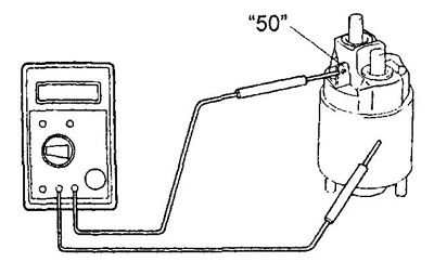
2. Checking the retracting winding of the traction relay.
Use an ohmmeter to check for continuity between the starter leads "50" And "WITH".
Otherwise replace the traction relay.
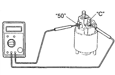
3. Checking the holding winding.
Using an ohmmeter, check that there is no continuity between the starter terminal "50" and hull.
Otherwise replace the traction relay.