
Preparation for disassembly
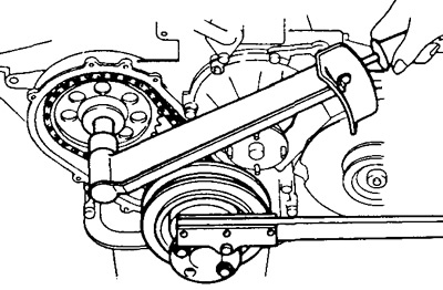
1. Remove the drive belt, after releasing the lock bolt of the generator housing.
2. Remove the fan and coolant pump pulley.
3. Remove the fuel pump.
4. Remove the distributor of ignition.
5. Remove an axis of yokes and bars of pushers.
Removing the timing chain and camshaft
1. Remove eight pushrods with a wire or magnet.
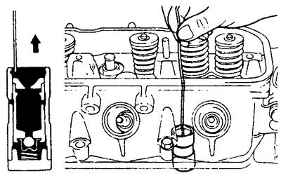
Warning: Store pushrods vertically and in order of installation.
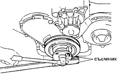
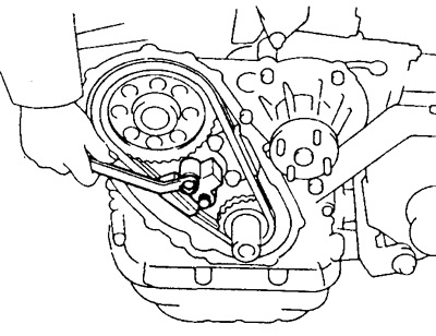
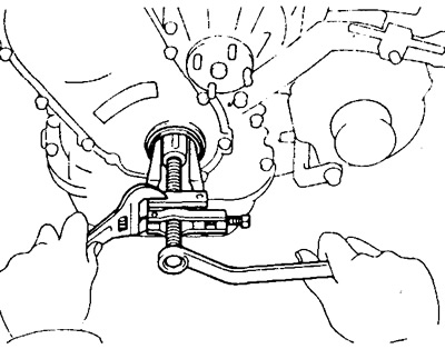
2. Remove the crankshaft pulley. Using a suitable tool, unscrew the pulley mounting bolt and use a puller to remove it.
 |  |
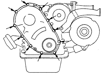
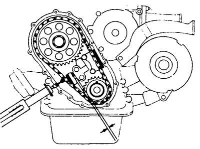
3. Turn away eleven bolts and remove a cover of a chain drive.
4. Check the chain slack using the special tool.
- Maximum sag - 13.5 mm with a force of 10 kg (98 N).
If the chain is too slack, replace the chain and sprockets.
5. Remove the two bolts and remove the timing chain tensioner.
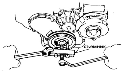
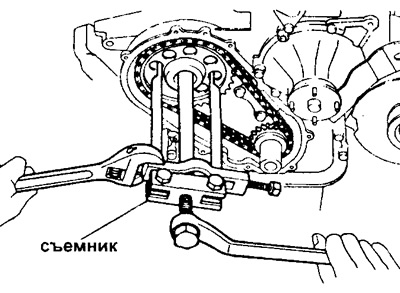
6. Remove the chain and sprockets.
A) Install the pulley on the crankshaft.
b) Using the tool, remove the camshaft bolt.
V) Remove the pulley from the crankshaft.
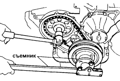
G) Using a puller, remove the camshaft sprocket along with the crankshaft sprocket and chain.
7. Turn out two bolts and remove the damper of a chain of a drive of the gas-distributing mechanism.
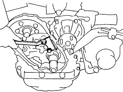
8. Remove the thrust washer by unscrewing the two bolts and carefully pull out the camshaft.
Attention: when removing the camshaft, do not damage the support bearings.
Assessment of the technical condition and repair of timing parts
1. Check the camshaft.
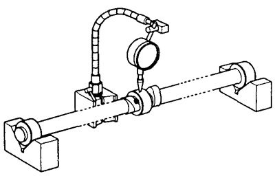
A) Lay the camshaft on prisms and measure the runout of the middle neck.
- Maximum runout - 0.06 mm
If the runout is more than acceptable, replace the camshaft.
b) Measure the height of the cams with a micrometer.
Cam height for motors:
2Y and 3Y YH YH/ACE models:
inlet valve:
- nominal - 38.185 - 38.285 mm
- minimum - 37.82 mm
exhaust valve:
- nominal - 38.443 - 38.543 mm
- minimum - 38.08 mm
Rest of Y series (for YH models):
inlet valve:
- nominal - 38.620 - 38.720 mm
- minimum - 38.26 mm
exhaust valve:
- nominal - 38.629 - 38.729 mm
- minimum - 38.27 mm
If the cam height is less than the minimum, replace the camshaft.
V) Measure the diameter of the necks with a micrometer.
Nominal neck diameters:
- No. 1 - 46.459 - 46.475 mm
- No. 2 - 46.209 - 46.225 mm
- No. 3 - 45.959 - 45.975 mm
- No. 4 - 45.709 - 45.725 mm
- No. 5 - 45.459 - 45.475 mm
If journal diameters are out of range, check bearing clearance
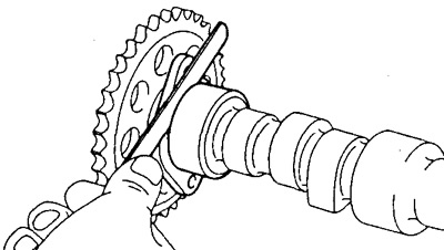
G) Install the thrust washer and sprocket onto the camshaft.
d) Install and tighten the sprocket bolt
- Tightening torque - 90 Nm
e) Using a feeler gauge, measure the clearance between the thrust washer and the camshaft.
- Nominal clearance - 0.07 - 0.22 mm
- Maximum clearance - 0.3 mm
If the clearance is greater than the maximum, replace the thrust washer. If necessary, replace the camshaft.
2. Check chain and sprocket.
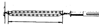
A) Measure the length of the chain by fully extending it as shown.
b) Repeat the measurements by pulling the chain in different places.
Maximum chain length at 5 kg tension (49 N) is 291.4 mm.
If the length is more than acceptable, replace the chain.
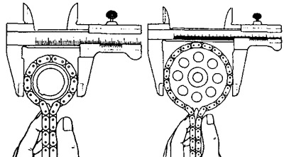
V) Using a vernier caliper, measure the diameter of the chain sprocket.
Minimum sprocket diameter:
- crankshaft - 59 mm
- distribution fat - 114 mm
If the diameter is less than the minimum, replace the chain and both sprockets.
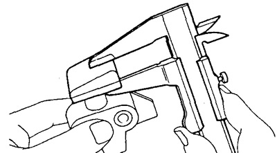
3. Check the chain tensioner by measuring its thickness with a vernier caliper.
tensioner thickness:
- nominal - 15.0 mm
- minimum allowable - 12.5 mm
If the thickness is less than the minimum, replace the tensioner.
4. If necessary, replace the chain tensioner plunger.
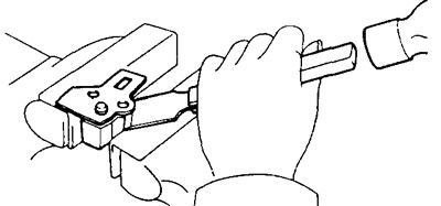
A) Using a scraper and hammer, remove the plate, being careful not to bend it.
b) Remove the tensioner plunger and spring.
V) Apply a light coat of engine oil to the tensioner body and plunger sliding surface.
G) Install the spring and new tensioner plunger into the housing.
d) Reinstall the plate.
e) Using a socket head and hammer, upset the plate.
5. Check the chain guide by measuring its thickness with a caliper.
damper thickness:
- nominal - 6.6 mm
- minimum allowable - 5.0 mm
If the thickness is less than the minimum, replace the damper.
6. Using a micrometer, measure the diameter of the pusher, the permissible value of which lies within: 21.387 - 21.404 mm.
If the diameter is outside these limits, check the gap between the cylindrical surface of the tappet and the wall of the tappet hole in the cylinder block.
7. If necessary, blow out the pushers.
Two types of pushers with hydraulic compensators are used: "Toyota" And "GM". Each of them uses its own purge method.
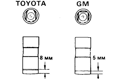
(Pushers type "Toyota")
Pump the pusher immersed in diesel fuel several times to remove air from the pusher housing.
(Pushers type "GM")
Dismantle and assemble the pusher immersed in diesel fuel. Using a leak tester (leak tester), install the pusher retaining ring and the pusher hose seat.
8. Perform a leak test.
Apply a force of 20 kg with the leak tester (196 N) on the plunger and measure the time it takes the plunger to move 1mm after it has moved about 2mm.
- Leakage time: 7-50s/1mm at 20°C.
Replacing the front crankshaft oil seal
Note: there are two methods (A and B) seal replacement.
A. With the chain cover removed, use a screwdriver and hammer to knock out the old oil seal. Using the correct size socket and hammer, install the new oil seal (moreover, its surface must be flush with the edge of the chain drive cover). Lubricate the seal lip with grease.
B. With chain cover installed, use a puller to remove the oil seal.
Lubricate the surfaces of the new oil seal with multipurpose grease. Using an appropriately sized socket or pipe and a hammer, install the new oil seal so that its surface is flush with the edge of the chain drive cover
Timing installation
1. Install the camshaft.
A) Carefully insert the camshaft into the cylinder block.
Attention: when installing, do not damage the camshaft bearings.
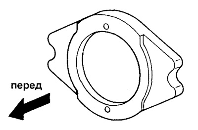
b) Install the thrust plate and tighten the two bolts.
- Tightening torque - 18 Nm
Attention: install the plate as shown in the figure.
2. Install the chain guide with two bolts.
- Tightening torque - 18 Nm
3. Install chain and sprockets.
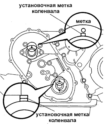
A) Align the crankshaft alignment mark vertically up (The piston of the 1st cylinder must be at TDC).
b) Align the mark on the camshaft sprocket with the mark on the thrust plate.
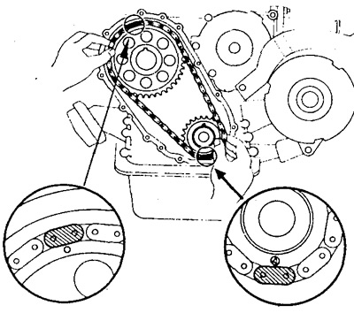
V) Engage sprockets with chain.
Note: Align the chain mark with the sprocket mark.
G) Install the chain and sprockets at the same time.
d) Install the pulley on the crankshaft.
e) Lubricate the threads and head of the camshaft mounting bolt with engine oil.
and) While holding the crankshaft pulley, install and tighten the camshaft sprocket bolt.
- Tightening torque - 90 Nm
h) Remove the pulley from the crankshaft.
4. Install and secure the chain tensioner with two bolts.
- Tightening torque - 18 Nm
5. Install the chain drive cover by installing a new gasket and securing the cover with 11 bolts.
- Tightening torque - 6 Nm
6. Install the crankshaft pulley.
Using a plastic hammer, fit the pulley onto the crankshaft toe.
Apply a coat of engine oil to the threads and head of the crankshaft pulley bolt. While holding the pulley from turning, install and tighten the pulley bolt.
- Tightening torque - 157 Nm
7. Using a wire or a magnet, insert the pushers into their sockets.
Final assembly and installation of attachments
1. Install the rods and rocker shaft assembly.
2. Install the ignition distributor.
3. Install the fuel pump.
4. Install the water pump pulley and fan.
5. Install and tension the drive belt.
6. Start the engine and check for leaks.
7. Check the oil level.