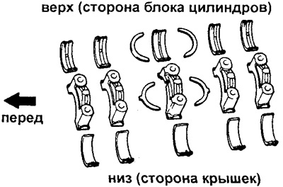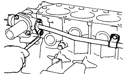
2. Unscrew nine bolts and one nut and remove the timing chain housing together with the gasket.
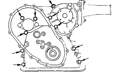
3. Unscrew the five bolts, remove the crankshaft rear oil seal housing, dust deflector and gasket.
4. Check the axial clearance of the lower connecting rod head.
- Nominal - 0.160 - 0.312 mm
- Maximum allowable - 0.35 mm
[This material is taken from a resource: www.toyotaman.ru]
If the gap is larger, replace the connecting rod.
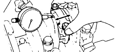
5. Remove the connecting rod caps and check the clearance in the connecting rod journals.
a) Using a punch or stamp, mark the caps and connecting rods.
b) Unscrew the nuts securing the covers.
c) Using a plastic hammer, tap the ends of the bolts and remove the connecting rod cap, holding the lower bearing shell from falling out of it.
d) Place pre-cut pieces of hose onto the connecting rod bolts to avoid damaging the crankshaft journals.
d) Clean the crankshaft bearings and journals.
e) Inspect each journal and bearing for chipping and scratches. If journals or bearings are damaged, replace the bearings. If necessary, replace the crankshaft.
g) Place a strip of plastic measuring tape on the crankshaft journal.
c) Install the connecting rod cover and tighten the nuts
- Tightening torque - 49 Nm
Caution: Do not turn the shaft.
i) Remove the connecting rod cover.
c) Measure the widest part of the print on the tape.
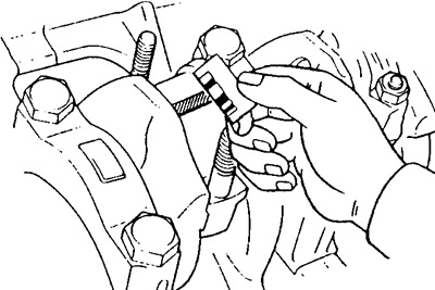
Gaps:
- Nominal (STD) - 0.020 -0.051 mm
- Reduced by 0.25 mm repair (U/S) - 0.021 - 0.067 mm
- Maximum gap - 0.10 mm
If the gap is larger, replace the bearing shells.
If necessary, replace the crankshaft.
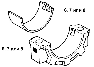
Note: If a standard bearing is used, it must be replaced with the same number as that marked on the connecting rod cap. There are three sizes of standard bearings, marked "6", "7" and "8" respectively.
Nominal liner thickness:
- Number "6" - 1.486 - 1.496 mm
- Number "7" - 1.496 - 1.494 mm
- Number "8" - 1.494 - 1.498 mm
l) Remove the measuring tape.
6. Remove the piston group.
a) Remove any carbon deposits from the cylinder edge using a countersink.
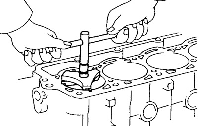
b) Cover the connecting rod bolts with pieces of hose.
c) Push out the piston group (piston, connecting rod and upper bearing).
Caution: Assemble the bearing shell, connecting rod and connecting rod cap of each cylinder together and arrange all piston sets in order.
7. Move the crankshaft back and forth with the lever and measure (using an indicator or feeler gauge) crankshaft axial clearance.
- Nominal clearance - 0.020 - 0.220 mm
- Maximum clearance - 0.300 mm
If the gap is larger, replace the thrust rings.
- Thrust ring thickness - 2.440 - 2.490 mm
8. Remove the main bearing caps and check the main bearing clearance.
a) Loosen the nuts of the main bearing cap bolts.
b) Using bolts, loosen the main bearing caps, remove the caps together with the liners, and also remove the lower thrust rings from the third journal cap.
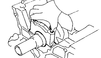
Note: Leave the upper bearing shells and thrust washers in place in the cylinder block. Arrange the main bearing caps and lower thrust washers in order.
c) Raise the crankshaft.
Caution: Leave the upper bearing shells and thrust washers in place in the cylinder block.
d) Clean the bearings and main journals.
d) Check each bearing and journal for chipping and scratches.
If the bearing or neck is damaged, replace the bearings.
If necessary, replace the crankshaft.
e) Place the crankshaft in the block bed.
g) Place a strip of plastic measuring tape on the main journal.
c) Install and tighten the main bearing caps.
- Tightening torque - 78 Nm
Caution: Do not turn the crankshaft.
i) Remove the covers.
c) Measure the widest part of the print on the tape.
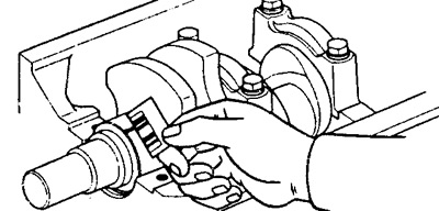
- Nominal (STD) - 0.020 -0.051 mm
- Reduced by 0.25 mm repair size (U/S) - 0.021 - 0.067 mm
- Maximum gap - 0.10 mm
If the gap is larger, replace the main bearings.
Note: When using standard liners, they must be replaced with those having the same number marked on the cylinder block. There are three sizes of standard liners, marked "1", "2" and "3" respectively.
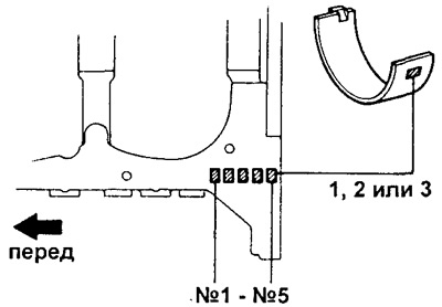
Nominal thickness of main bearings:
- Number "1" - 1.986 - 1.990 mm
- Number "2" - 1.990 - 1.994 mm
- Number "3" - 1.994 - 1.998 mm
l) Remove the plastic tape.
9. Remove the crankshaft, then remove the upper bearing shells and upper thrust half rings from the cylinder block and arrange them in order.