
Disassembly
1. Remove the carburetor.
2. Remove the intake and exhaust manifolds.
3. If necessary, separate the intake and exhaust manifolds by unscrewing and removing the connecting bolts.
4. Remove the valves: using a puller, compress the valve spring and remove the two crackers; then remove the valve disc (or valve rotator), spring, spring seat, valve and oil seal. Arrange the removed parts so that they are not mixed up during installation.
5. If necessary, remove the following parts:
A) Coolant outlet pipe.
b) Heater outlet.
V) Rear flange of the cylinder head.
Checking and cleaning parts and elements of the cylinder head
1. Clean the bottoms of the pistons and the plane of the block connector.
A) Rotate the crankshaft and move each piston to TDC. Clean the piston bottoms with a scraper.
b) Remove the rest of the gasket from the block connector.
V) Blow out the oil passages and bolt holes with compressed air.
Warning: Use eye protection when using compressed air.
2. Remove the rest of the gaskets from the surfaces of the block head and manifolds with a scraper.
Attention: do not damage the cleaned surfaces.
3. Use a wire brush to remove deposits from the surfaces of the combustion chambers so as not to damage the surface of the cylinder head connector.
4. Clean the valve guide holes.
5. Clean the cylinder head thoroughly with a soft brush and solvent.
Attention: do not wash the head in hot solvents, as this may damage the part.
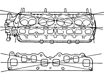
6. Using a precision ruler and probes, check up the plane of sockets of a head of the block of cylinders along the lines designated in drawing. Maximum non-flatness:
- On the gas joint connector - 0.15 mm
- On the intake and exhaust manifold connector - 0.10 mm
If the measured value is greater than the specified maximum, replace the head or regrind its surface (but not more than 0.30 mm).
7. Using penetrating dye, check combustion chambers, inlet and outlet ports, and connector surfaces for cracks. If there are cracks, replace the head.
8. Use a scraper and a wire brush to clean carbon deposits from the valve disc.
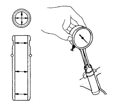
9. Using a bore gauge, measure the valve guide bore diameters.
- Valve guides inner diameter - 8.010 - 8.030 mm
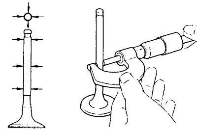
Using a micrometer, measure the diameters of the valve stems at three different levels.
Valve stem diameters:
- Intake - 7.970 - 7.985 mm
- Exhaust - 7.965 - 7.980 mm
By subtracting the obtained valve stem diameters from the corresponding guide bushing bore diameters, determine the clearance in the bushings.
Nominal clearance:
- intake valve - 0.025 - 0.060 mm
- exhaust valve - 0.030 - 0.065 mm
Maximum allowable clearance:
- intake valve - 0.10 mm
- exhaust valve - 0.12 mm
10. If necessary, replace the guide bush.
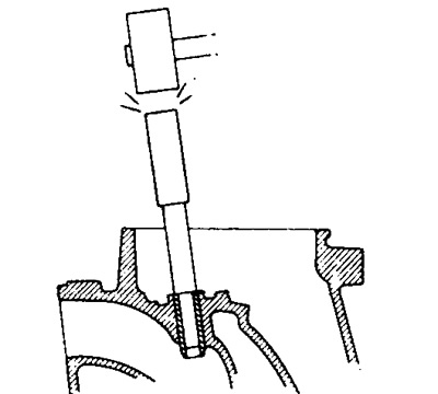
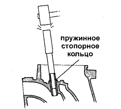
A) Using a pin and hammer, loosen the guide bushing, making sure the bushing retaining ring is removed.
b) Slowly heat the cylinder head in a water bath to a temperature of 80-100°C.
V) Using a punch and hammer, knock out the guide bushing.
G) Using a bore indicator, measure the hole in the block head for the guide bushing.
d) Pick up a new nominal bushing (STD) or repair size increased by 0.05 mm (O/S).
If the hole for the sleeve in the cylinder head is larger than 13.027 mm, then ream the hole to the repair size (13.050-13.077 mm).
If the bore exceeds 13.077 mm, replace the cylinder head.
e) Slowly heat the block head to 80-100°C.
and) Using a drift and hammer, drive in the new valve sleeve until the circlip snaps into place.
h) Using an 8mm reamer, ream the bushing hole until the recommended clearance is obtained "bushing bore - new valve diameter".
11. Check and grind valves.
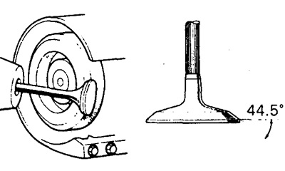
A) Grind the valve bevel to remove signs of wear and deposits.
b) Check valve face angle (44,5°).
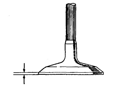
V) Check the thickness of the valve disc collar.
The nominal thickness of the valve disc collar is:
- For the intake valve - 1.0-1.4 mm
- For the exhaust valve - 1.3-1.7 mm
The minimum thickness of the valve disc collar is:
- For the intake valve - 0.5 mm
- For exhaust valve - 0.8 mm
If the minimum belt thickness is less than the specified values, replace the valve.
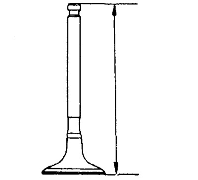
G) Check overall valve length. The nominal and minimum valve lengths are:
- For intake - 108.2 mm and 107.7 mm
- For graduation - 108.5 mm and 108.0 mm
If valve length is less than minimum, replace valve.
d) If the valve stem end is worn, grind the end until the wear is removed or replace the valve.
12. Check and clean valve seats.
A) Using a 45°cutter, machine the valve seats.
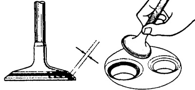
b) Check the seating of the valve. Apply a thin coat of paint (white lead) on the chamfer of the valve, put the valve and press it lightly, but do not rotate.
V) Check valve and seat:
If a trace of paint appears on all 360°of the valve seat, then the poppet and valve seat are concentric.
If not, regrind the seat. Check the contact mark in the middle of the valve chamfer:
Contact width 1.2-1.6mm for intake and exhaust valves.
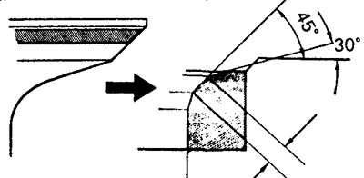
If necessary, make adjustments as follows:
(1) if the contact mark is too high on the valve face, use the 30°and 45°cutters to correct the contact mark.
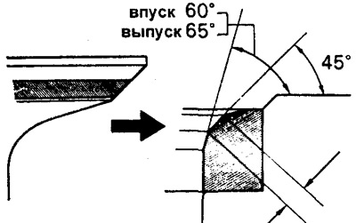
(2) if the contact mark is too low on the valve face, then the 60°and 45°cutters for the inlet valve and the 65°and 45°cutters for the exhaust valve must be used to correct the valve seat.
G) Lap the valve to the seat using abrasive paste.
d) After lapping, clean (rinse) valve and seat from abrasive.
13. Check valve springs.
A) Using a square, check that the valve springs are not perpendicular.
- Maximum non-perpendicularity - 2 mm
For large misalignments, replace the valve spring.
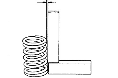
b) Using a caliper, measure the free length of the spring.
- Spring length - 47.0 mm
If the spring length differs from the specified value, replace the spring.
V) Using a spring tester, measure the force required to compress the spring to 40.6 mm:
- Force - 282-345 N
If the measured value is out of range, replace the spring.
14. Check up a yoke and an axis of yokes.
A) Check the condition of the working surface of the rocker in contact with the valve stem.
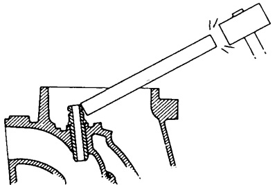
b) Check the clearance between the rocker arm and the rocker shaft by moving the rocker arm as shown in the illustration.
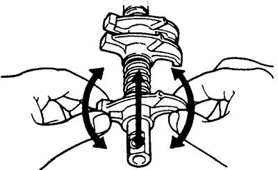
If movement is felt, disassemble the rocker arm assembly and check it.
V) Disassemble the rocker arm/axle assembly by placing the rocker arms in the appropriate order. If there is wear on the contact surface of the rocker heads, remove the wear with a grinder or replace the rocker.
G) Check clearance between rocker arm axle and rocker arm:
Using a bore gauge, measure the inside diameter of the rocker arm.
- Rated - 18.500 - 18.515 mm
Using a micrometer, measure the diameter of the rocker shaft.
- Rated - 18.474 - 18.487 mm
Subtracting the diameter of the axis of the rocker arms from the diameter of the bore of the rocker arm, determine the clearance.
- standard - 0.013-0.041 mm
- maximum allowable - 0.08 mm
If the clearance exceeds the maximum value, replace the rocker arm and axle.
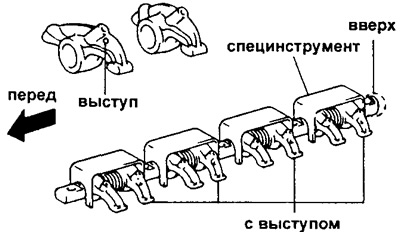
d) Assemble the knot "rocker arms - axis of rocker arms".
Make sure the rear end of the rocker shaft is in the correct position, assemble the rocker arms and springs as shown and hold them together with the tool.
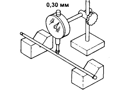
15. Check push rods.
A) Lay the rods on the prisms.
b) Using an indicator, check the straightness of the rods.
The maximum deviation from straightness is 0.30 mm.
If the deviation is greater, replace the stem.
Check the rod oil hole. If the hole is clogged, blow it out with compressed air.
16. Check intake and exhaust manifolds. Using a precision ruler and feeler gauge, check for warpage (flatness) collector contact surfaces.
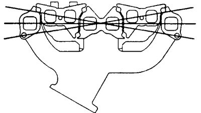
- The maximum allowable flatness is - 0.40 mm
At high values of this indicator, replace the collector.