
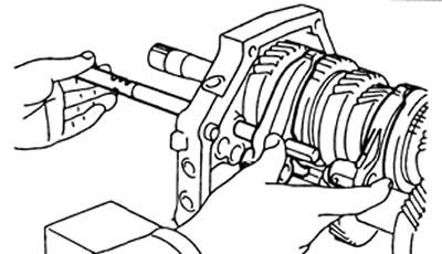
A) Install the output shaft into the intermediate bearing by pushing it in and lightly tapping the intermediate bearing.
b) Establish a lock ring of the central bearing of a secondary shaft.
Note: Make sure the circlip is flush with the intermediate bearing surface.
2. Installation of the input shaft.
A) Apply grease to the 13 needle bearing rollers and insert the needle rollers into the input shaft center hole.
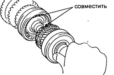
b) Install the input shaft on the output shaft, ensuring that the grooves of the synchronizer ring match the synchronizer crackers.
3. Installation of the intermediate shaft.
A) Install the circlip on the intermediate shaft rear bearing.
b) Install the intermediate shaft and rear shaft bearing into the intermediate bearing.
V) While holding the intermediate shaft, press the rear shaft bearing into the intermediate bearing.
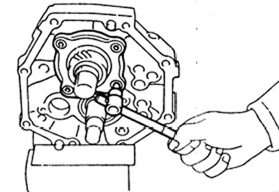
4. Establish the holder of the back bearing of a secondary shaft and by means of a special key tighten a bolt of fastening.
Tightening torque - 18 N.m
5. Install the reverse idle gear and its shaft onto the intermediate support. Install the shaft stop and tighten the mounting bolt.
Tightening torque - 17 N.m
6. Establish an arm of the scenes of inclusion of transfer of a backing and tighten two bolts of fastening.
Tightening torque - 18 N.m
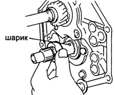
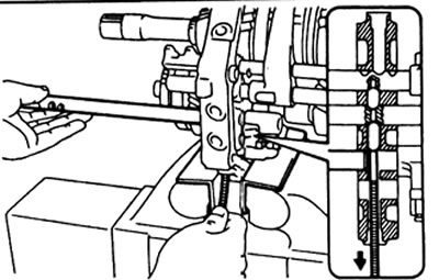
7. Insert the ball into the intermediate shaft and install the spacer.
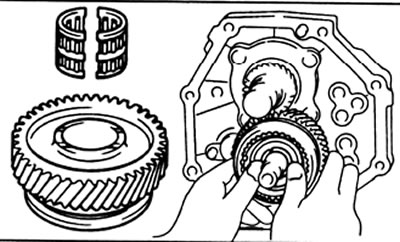
8. Installation of the fifth gear of the intermediate shaft assembly with synchronizer No. 3 and needle bearing.
A) Apply gear oil to the needle bearing rollers.
b) Install the 5th gear assembly with synchronizer #3 and needle bearing.
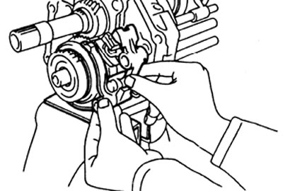
9. Installation of the ring and hub of the synchronizer of the fifth gear.
A) Put the synchronizer ring on the hub.
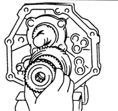
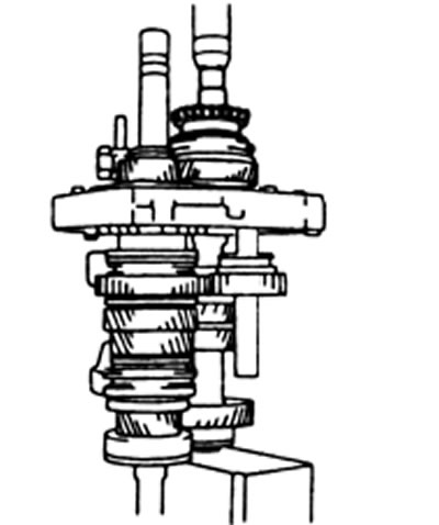
b) Remove the intermediate support assembly from the vise and install as shown in the figure.
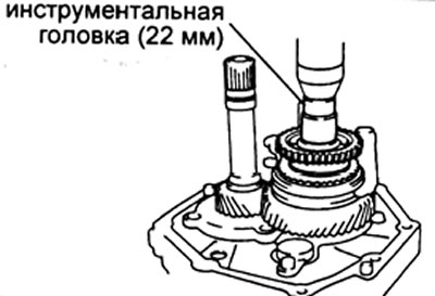
V) With press and tool head (22 mm), install the 5th gear synchronizer hub so that the grooves of the synchronizer ring fit exactly into the synchronizer lugs.
G) Install the intermediate support in a vise.
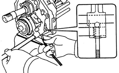
10. Installing the retaining ring.
A) Select the retaining ring so that the minimum axial clearance is provided.
| Label | Thickness, mm |
| A | 2,80-2,85 |
| IN | 2,90-2,85 |
| WITH | 2,90-2,95 |
| D | 2,95 - 3,00 |
| E | 3,00 - 3,05 |
| F | 3,05-3,10 |
| G | 3,10-3,15 |
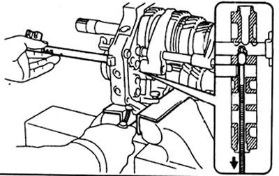
b) Using a copper rod and a hammer, install the retaining ring on the intermediate shaft.
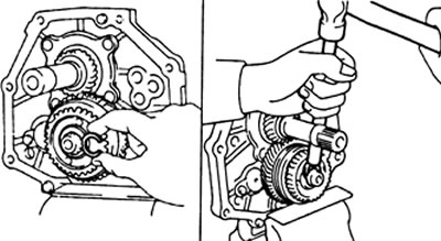
11. Using a feeler gauge, measure the axial clearance of the fifth gear of the intermediate shaft.
Nominal clearance - 0.10 - 0.30 mm
Maximum clearance - 0.30 mm
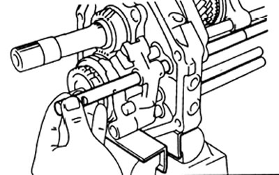
12. Installing the shift rod No. 2 and the fork No. 1 and No. 2 gear shifting.
A) Install shift forks #1 and #2.
b) Install shift rod #2 through intermediate support, and shift forks #1 and #2.
V) Install and tighten the #2 shift fork mounting bolt.
Tightening torque - 20 N.m
13. Installing the rod No. 1 gear shift.
A) Apply grease to lock pin #2 and install it to shift rod #1.
b) Using a magnetic rod, install locking pin #1 into the hole in the intermediate support.
V) Install shift rod #1 through intermediate support and shift fork #1.
G) Install and tighten the #1 shift fork mounting bolt.
Tightening torque - 20 N.m
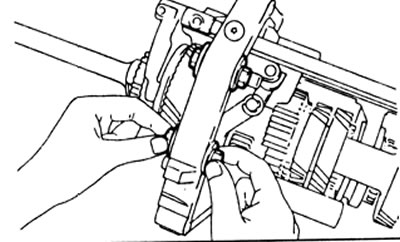
14. Installing the gearshift rod No. 3 and the backstage of the reverse gear assembly with the fork.
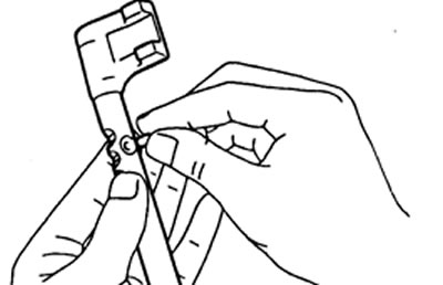
A) Install the pin and yoke on the reverse gear selector, and secure them with two circlips.
b) Install the reverse gear shift link to the link bracket.
V) Apply grease to lock pin #4 and insert it into shift rod #3.
G) Using a magnetic rod, install locking pin #3 into the hole in the intermediate support.
d) Install the #3 shift rod through the intermediate support and the reverse gear fork.
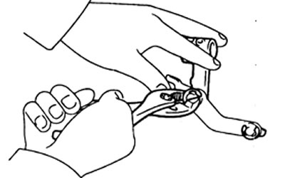
e) Using a punch and hammer, drive the pin into the reverse gear fork.
15. Installing the head of the reverse gear engagement rod, the fifth gear engagement fork, gearshift rods No. 4 and No. 5.
A) Slide the reverse gear knob onto the #3 gear shift rod.
b) Install shift fork #3.
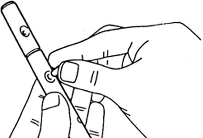
V) Using a magnetic rod, insert the ball into the head of the reverse gear shift rod.
G) Install shift rod #4 as shown.
d) Using a magnetic rod, insert the locking ball #1 into the intermediate support.
e) Install shift rod #4 through intermediate support.
and) Using a beard and hammer, drive the pin into the #3 shift fork.
h) Install the #5 shift rod through the reverse gear rod head and intermediate support.
And) Using a punch and hammer, drive the pin into the head of the reverse gear shift rod.
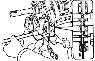
16. Using a copper rod and a hammer, install the three circlips onto the shift rods.

17. Installation of screw plugs.
A) Insert four balls and springs into the intermediate support.
Note: insert the short spring from below the intermediate support.
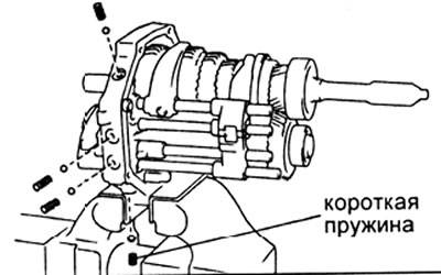
b) Apply sealant to the threads of the plugs.
Sealant: THREE BOND 1344, LOCTITE 242 or equivalent.
V) Insert the screw plugs and tighten them with a socket wrench under the hexagon socket bolt.
Tightening torque - 19 N.m
18. Remove the intermediate support from the vise, unscrew the bolts, remove the nuts and plate washers.
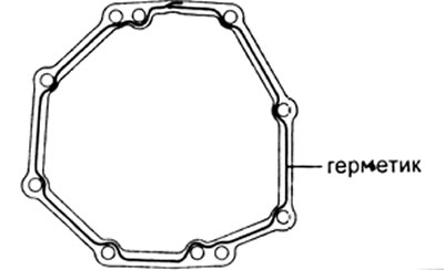
19. Install the gearbox housing,
A) Apply sealant to the gearbox housing (see picture).
Sealant: THREE BOND 1231 or equivalent.

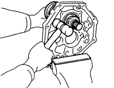
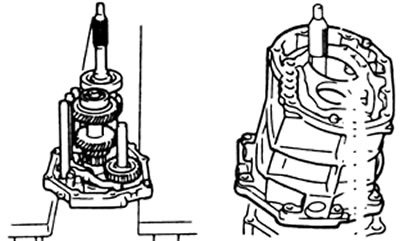
b) Install the intermediate support as shown in the figure.
V) Install the gearbox housing on the intermediate support as shown in the figure.
20. Installing the support holder. pin of the input shaft.
A) Install the retaining rings on the bearings of the input and intermediate shafts.
b) Install the bearing holder with a new gasket.
V) Apply sealant to the threads of the holder mounting bolts.
Sealant: THREE BOND 1344, LOCTITE 242 or equivalent.
G) Install and tighten the bolts.
Tightening torque - 17 N.m
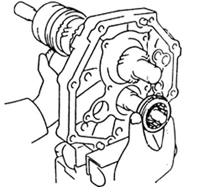
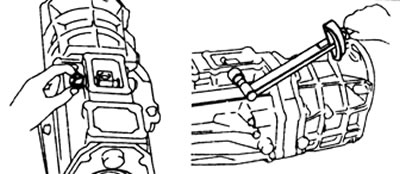
21. Installing the transfer case adapter, shaft and shift lever housing.
A) Apply sealant to the transfer case adapter as shown.
Sealant: THREE BOND 1231 or equivalent.
b) Install the transfer box adapter and secure it with eight bolts.
Tightening torque - 37 N.m
V) Install the shift lever housing into the transfer case adapter as shown in the illustration.

G) Insert the shift lever shaft into the transfer case adapter through the shift lever housing.
d) Install and tighten the shift lever housing bolt.
Tightening torque - 38 N.m
e) Using the special tool, install and tighten the plug.
Tightening torque - 37 N.m
22. Installing the screw plug.
A) Apply sealant to the threads of the plug.
Sealant: THREE BOND 1344, LOCTITE 242 or equivalent.
b) Install the locking ball, spring and plug. Tighten the stopper.
Tightening torque - 19 N.m
23. Check after installing the transfer box adapter.
A) Check that the input and output shafts rotate without binding.
b) Make sure all gear shifts are smooth and crisp.
24. Installation of limit pins.
A) Install the black pin on the reverse and fifth gear side.
b) Insert another stop pin and tighten the pins.
Tightening torque - 27 N.m
25. Install the shift lever cover and new gasket. Install and tighten the four cover screws.
Tightening torque - 18 N.m
26. Install the transfer case control lever cover and new gasket. Install and tighten the four cover screws.
Tightening torque - 18 N.m
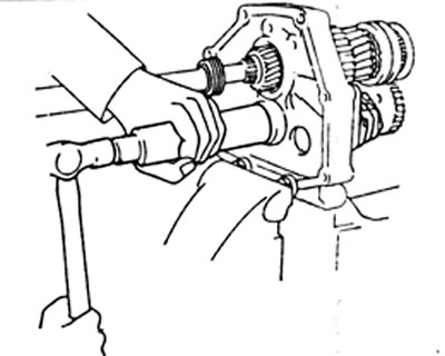
27. Installing the clutch housing.
A) Install the clutch housing.
b) Apply sealant to the threads of the crankcase mounting bolts marked "A" on the image.
Sealant: THREE BOND 1344, LOCTITE 242 or equivalent.
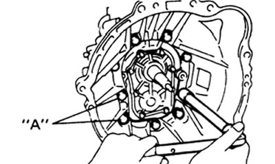
V) Install and tighten the nine mounting bolts.
Tightening torque - 37 N.m
28. Install the reversing light switch.
Tightening torque - 37 N.m
29. Install the clutch release fork and bearing.