
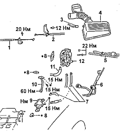
4A-FE (automatic transmission)
1 - accelerator cable,
2 - throttle valve control cable (automatic transmission),
3 - intake air temperature sensor connector,
4 - air filter cover with air duct,
5 - vacuum hose,
6 - wiring harness,
7 - coolant hose,
8 - gasket,
9 - exhaust gas recirculation valve (EGR),
10 - EGR system tube,
11 - air hose,
12 - throttle body.
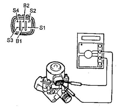
1. Remove the valve.
2. Check the resistance of the valve coil/
Measure the resistance between the terminals with an ohmmeter ("B1" - "S1"..."S4", "AT 2" - "S1"..."S4").
- Rated resistance - 20-23 Ohm
If the resistance is not as specified, replace the valve.
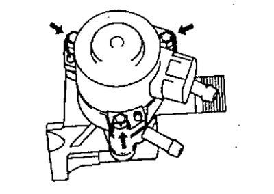
3. Remove the actuator.
4. Check valve operation.
A) Apply battery voltage to terminals "IN 1" And "AT 2" and, alternately grounding the conclusions "S4"-"S3"-"S2"-"S1" in that order, make sure the valve opens gradually.
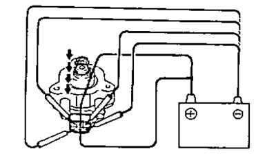
b) Apply battery voltage to terminals "IN 1" And "AT 2" and, alternately grounding the conclusions "S1"-"S2"-"S2"-"S3"-"S4" in that order, make sure the valve closes gradually.
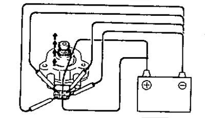
If the valve does not function as described, replace it.
5. Install the actuator.
6. Install the electro-pneumatic valve.