



Attention. During diagnostics, two main modes are used: current self-diagnosis and testing.
Current self-diagnosis mode
To obtain the output diagnostic code, the following procedures must be performed.
1. Check the initial conditions.
a) Battery voltage is not less than 11 volts.
b) The throttle valve is completely closed (the "IDL" terminals of the throttle position sensor are shorted).
c) The gearbox control lever is in neutral position.
d) All additional equipment is turned off,
d) The engine is warmed up to normal operating temperature.
2. Turn on the ignition, but do not start the engine.
3. Short-circuit the diagnostic connector terminals "TE1" and "E1".
4. Read the diagnostic code by the number of flashes, "CHECK" display. (Diagnostic codes see below in the table).
Form of diagnostic codes
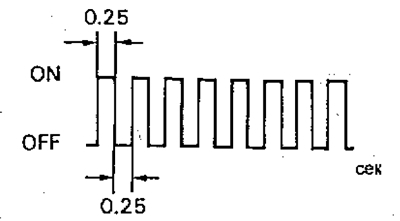
a) Normal operation of the system (absence of malfunction). The light board lights up and goes out 2 times per second.
b) Indication of a fault code. If a fault is present, the light panel flashes every 0.5 seconds. The first sequence of flashes corresponds to the first digit of the diagnostic code, which consists of two digits. After a pause of 1.5 seconds, the second sequence of flashes is output, corresponding to the second digit of the code. If there are two or more fault codes, an interval of 2.5 seconds is set between them when output. After all the codes have been output, there is a pause of 4.5 seconds, and then they are all repeated while the "TE1" and "E1" terminals of the diagnostic connector are shorted.
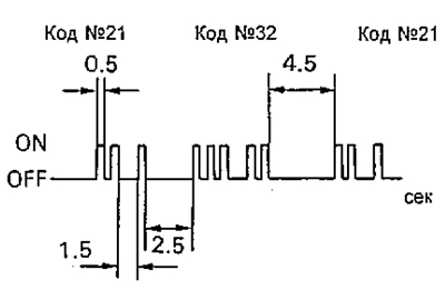
Note: In case of several fault codes, their indication starts with the lower code and continues in ascending order.
c) Two-stage algorithm for detecting faults.
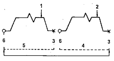
1 - fixing a fault for the first time (pre-memorization),
2 - fixing the fault for the second time (illumination of the light board),
3 - ignition off,
4 - second cycle,
5 - first cycle,
6 - ignition on.
When recording some codes, a two-stage algorithm is used. It consists of the fact that when a malfunction occurs for the first time, its code is temporarily recorded in the memory of the electronic control unit. If the same malfunction is recorded during the second test drive, then in this case the light panel lights up. The second test drive is repeated in the same mode. (However, between the first and second test drive cycles the ignition must be switched off). During self-diagnosis in test mode, the light panel turns on at the first sign of a malfunction.
5. After completing diagnostics, disconnect the wire from the diagnostic connector.
Test mode
Note: Compared with the normal self-diagnosis mode, the self-diagnosis in the test mode has increased sensitivity to detecting faults.
This allows you to identify faults in the electrical circuits of the starting system, the air conditioning system, and also in the electrical circuit of the start inhibit switch.
Self-diagnostics in test mode allows you to identify faults that are also recorded by regular self-diagnostics.
(The original article is on the portal: ToyotaMan.ru)
To obtain the output diagnostic code in the test mode, the following procedures must be performed.
1. Check the initial conditions.
a) Battery voltage is not less than 11 volts.
b) The engine is warmed up to normal operating temperature.
c) The gearshift lever is in neutral position.
d) All additional equipment is switched off.
2. Short-circuit the "TE2" and "E1" terminals of the diagnostic connector using a suitable wire, then turn on the ignition, and the self-diagnosis system will operate in test mode.
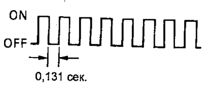
Note: confirmation that the self-diagnostic system is operating in the testing mode is the blinking of the "CHECK" display when the ignition is on. In this case, the time between the end and the beginning of successive pulses (flashes), i.e. the pulse duty cycle, is 0.13 s.
3. Start the engine and drive the vehicle at a speed of 10 km/h or higher.
4. Simulate situations in which the malfunction occurs.
5. Using a suitable wire, short-circuit the "TE1" and "E1" terminals of the diagnostic connector.
6. Read the diagnostic codes by the number of flashes of the "CHECK" light.
7. After completing diagnostics, disconnect the wires from the diagnostic connector.
Attention:
- - The system will not enter the testing mode if the "TE2" and "E1" terminals are shorted after the ignition is turned on.
- - At vehicle speed of 5 km/h and below, code No.42 will be displayed (speed sensor), which is not a sign of a malfunction.
- - If the engine does not turn over with the starter, code No.43 (starter) will be displayed, which is not a sign of a malfunction.
- - If the automatic transmission control lever is in the positions: "D", "2", "L" or "R", or if the air conditioner is on, or if the accelerator pedal is fully depressed, then code No.51 ("air conditioner on") is displayed, which, however, is not a sign of a malfunction.
4. Read the diagnostic code by the number of blinks (flashes) of the "CHECK" indicator lamp. (Diagnostic codes see below in the table).