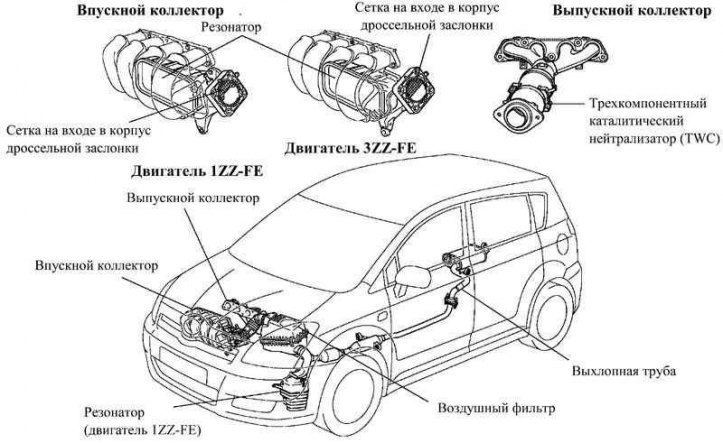
Pic. 2.18. Intake and exhaust system for 1ZZ-FE and 3ZZ-FE engines
To reduce weight and heat from the cylinder head, the intake manifold is made of plastic. As a result, it was possible to reduce the intake air temperature and increase the filling factor.
A resonator is placed in the intake duct for dynamic wave tuning of the air flow at the intake and for increasing the power characteristics of the engine in the range of medium speeds.
To reduce weight, the exhaust manifold is made of stainless steel.
The exhaust manifold with the front part of the exhaust pipe, as well as the rear and front parts of the exhaust pipe, are connected by ball joints, which have a simple and reliable design.
In order for the airflow to be laminar, a mesh is installed between the intake manifold and the throttle body.
A three-way catalytic converter is integrated into the exhaust manifold.
Differences from previous models
The intelligent electronic throttle control system ETCS-i has excellent performance.
Electric throttle body installed.
The metal clips on the air filter housing have been replaced with plastic ones. This has increased the amount of recyclable materials.
To reduce the noise level, a resonator is included in the design of the intake tract (only in 1ZZ-FE engine).
Maintenance recommendation
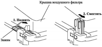
Pic. 2.19. Air filter cover removal diagram
To remove the air filter cover, follow the steps below (pic. 2.19).
1. Raise the clamp to a vertical position.
2. Move the clamp forward.
3. Remove the air filter cover.
Throttle body
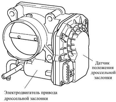
Pic. 2.20. throttle body
The throttle position is controlled by a DC motor with minimal power consumption. To control the throttle opening angle, the engine ECU changes the direction and strength of the current flowing through the throttle motor.
Electric throttle body installed; this design provides exceptional throttle control capability.
An exhaust manifold
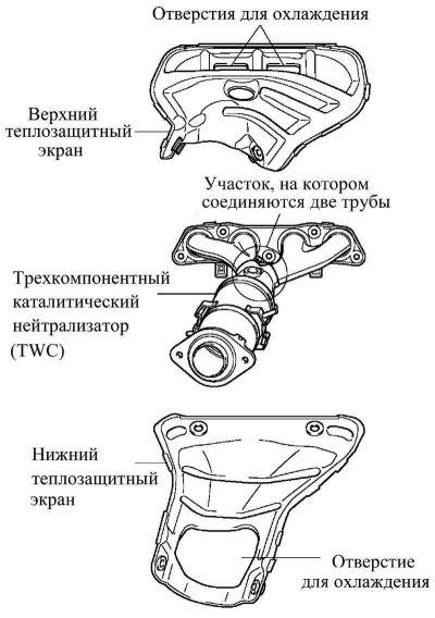
Pic. 2.21. An exhaust manifold
The exhaust manifold consists of short pipes and a section where two pipes are connected. This design allows the three-way catalytic converter to quickly warm up and enter the operating mode.
The heat shield has openings through which cooling air enters to reduce the temperature of the exhaust manifold.
The exhaust manifold houses a three-way, ultra-thin-wall, small-cell, ceramic-supported catalytic converter. Thanks to this constructive solution, the time for warming up the converter and reaching its operating mode in accordance with the requirements of Euro IV and European exhaust gas toxicity standards during cold engine start has been significantly reduced.
Exhaust pipe
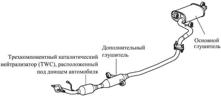
Pic. 2.22. Exhaust pipe
The exhaust manifold has a three-way catalytic converter (TWC) with a ceramic carrier with ultra-thin walls and small mesh sizes, meeting the requirements of Euro IV standards.
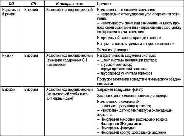
Table 2.16. Possible malfunctions and their causes in the exhaust system