
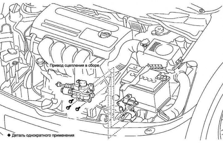
Pic. 3.30. Clutch drive assembly (C251 A)
Clutch drive assembly (C251 A) shown in fig. 3.30.
Disconnect the negative terminal from the battery terminal.
Removing the clutch drive assembly
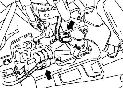
Pic. 3.31. Clutch travel sensor connector
Disconnect the clutch travel sensor connector (pic. 3.31).
Note. Do not pull hard on the connector as this may damage the wires.
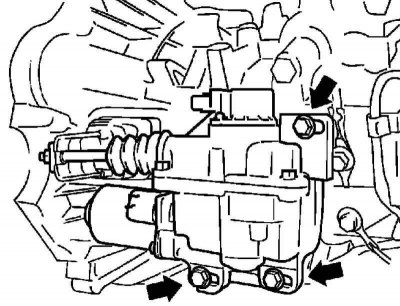
Pic. 3.32. Clutch drive mount
Remove the 3 bolts and remove the clutch drive assembly (pic. 3.32).
Note. To avoid injury to fingers, the fastening bolts should be unscrewed carefully, because. the clutch actuator is under load from the clutch basket.
Note. Work must be done carefully so as not to drop or hit the clutch actuator.
Note. It is forbidden to loosen the pusher fastening nut.
Installing the clutch drive assembly
Connect the clutch travel sensor connector and motor connector.
Connect the negative terminal to the battery terminal.
Adjust clutch position (full clutch position).
Disconnect the negative terminal from the battery terminal.
Disconnect the clutch travel sensor connector and motor connector.
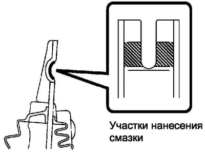
Pic. 3.33. Lubrication points
Apply grease to the hatched areas of the clutch release fork (pic. 3.33).
Install the tappet into the U-shape of the release fork and insert 3 bolts into the holes in the clutch housing.
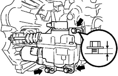
Pic. 3.34. Gap between clutch housing and bolt heads
Note. There must be a gap of 3 mm between the clutch drive housing and the bolt heads (pic. 3.34).
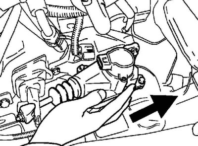
Pic. 3.35. Moving the clutch actuator assembly towards the left side of the engine compartment
Carefully move the clutch actuator assembly towards the left side of the engine compartment, keeping it from tilting, until the protrusion of the pusher mounting nut is aligned with the notch of the clutch release fork (pic. 3.35).
Note. When combining the nut with the fork, do not apply significant force.
Note. Make sure the lug of the nut is securely engaged in the notch of the yoke.
Tighten the 3 bolts by hand while holding the clutch actuator assembly.
Note. The clutch actuator must be held until all 3 bolts are fully tightened.
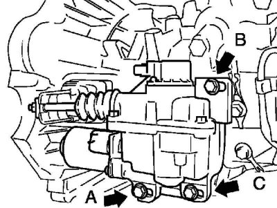
Pic. 3.36. Bolts of fastening of a drive of coupling
Torque tighten the 3 bolts in the following order: A, B, then C (pic. 3.36).
Tightening torque: 17 Nm.
Connect the clutch travel sensor connector and motor connector.
Connect the negative terminal to the battery terminal.
Initialize the MMCP ECU.
Set up MMCP.
Calibrate the timing positions.