
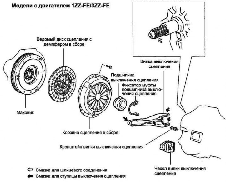
Pic. 3.42. Clutch components
Removing the clutch release fork
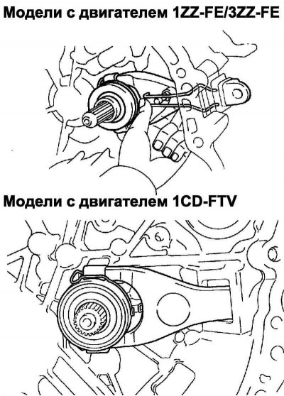
Pic. 3.43. Removing the clutch release fork
Remove the clutch release fork with the clutch release bearing from the manual gearbox housing in the final drive unit (pic. 3.43).
Removing the clutch release bearing
Remove the clutch release bearing from the clutch release fork.
Removing the clutch release fork bracket
Remove the clutch release fork bracket from the front final drive case.
Remove the clutch release bearing retainer.
Remove the clutch release fork cover.
Removing the clutch basket assembly
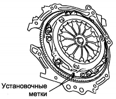
Pic. 3.44. Labels on the clutch basket
Mark the clutch basket and flywheel so that they are in their original position during reassembly (pic. 3.44).
Loosen the mounting bolts by loosening them gradually one turn at a time until the spring load is reduced.
Turn out bolts of fastening and remove a basket of coupling.
Note. Work must be done carefully so as not to drop the clutch disc.
Remove the clutch disc with damper assembly.
Note. Make sure that the friction linings of the driven disk, the working surfaces of the pressure disk and the flywheel do not get oil and foreign particles.
Check of a condition of a conducted disk of coupling
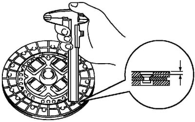
Pic. 3.45. Rivet depth measurement
Measure the depth of the rivet with a caliper (pic. 3.45).
Minimum allowable rivet penetration: 0.3 mm.
If necessary, replace the clutch disc with damper assembly.
Install the clutch disc into the gearbox.
Pic. 3.46. The correct position of the clutch disc during installation
Note. When installing, make sure that the clutch disc with damper assembly is correctly oriented.
Use a dial gauge to measure the radial runout of the damper clutch disc assembly.
The maximum allowable value of the radial runout: 0.8 mm.
If necessary, replace the clutch disc with damper assembly.
Checking the clutch basket assembly
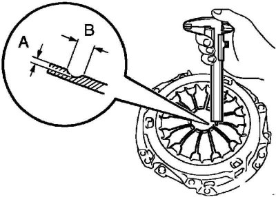
Pic. 3.47. Depth measurement of aperture blades
Using a caliper, measure the depth and width of the opening formed due to wear on the petals of the diaphragm spring (pic. 3.47).
MCP in the block with the main gear of type С251А.
- A (Depth): 0.3 mm.
- IN (Width): 6.0 mm.
The maximum allowable value of the MCP in the block with the final drive type C251 / E358.
- A (Depth): 0.5 mm.
- IN (Width): 6.0 mm.
If necessary, replace the clutch basket assembly.
Flywheel check
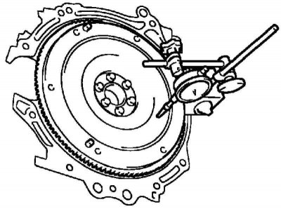
Pic. 3.48. Flywheel runout measurement
Measure the flywheel radial runout with a dial gauge (pic. 3.48).
The maximum allowable value of the radial runout: 0.1 mm.
Replace flywheel if necessary.
Check of the bearing of deenergizing of coupling assy
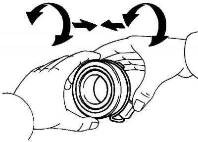
Pic. 3.49. Checking the clutch release bearing
Check if it's free (no sticking) the clutch release bearing moves, rotating and simultaneously moving in the axial direction (pic. 3.49).
Check the bearing for excessive wear or damage.
Note. If necessary, replace the clutch release bearing assembly.
Installation of a conducted disk of coupling with a damper assy
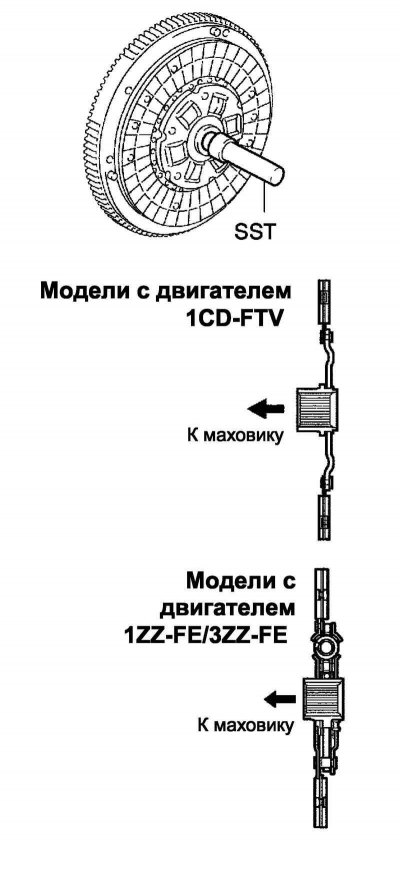
Pic. 3.50. Scheme of installation of the driven clutch disc with damper assembly
Insert Damper SST into Damper Clutch Disc Assembly and install disc to flywheel (pic. 3.50).
Note. When installing, make sure that the clutch disc with damper assembly is correctly oriented.
Installing the clutch basket assembly
Align the alignment marks on the clutch basket and flywheel.
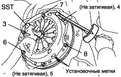
Pic. 3.51. The order of tightening the bolts of the clutch basket
Tighten 6 bolts in the sequence shown in Figure 3.51. Start with the bolt next to the drive pin at the top.
Tightening torque: 19 Nm.
Slightly move the SST up, down, right and left to make sure the driven disc is properly centered, then tighten the bolts.
Checking and adjusting the clutch basket assembly
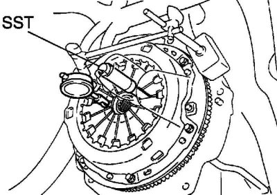
Pic. 3.52. Measuring the position of the ends of the petals of the diaphragm spring
Using an indicator with a roller, measure whether the ends of the petals of the diaphragm spring lie in the same plane (pic. 3.52).
The maximum allowable deviation from the plane: 0.5 mm.
If the value is not correct, align the diaphragm spring tab with the SST tool.
Installing the clutch release bracket
Install the clutch release fork bracket to the front transaxle case. Tightening torque: 37 Nm.
Installing the clutch release fork
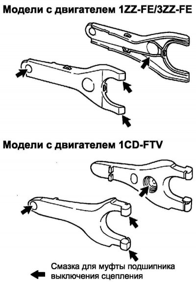
Pic. 3.53. Grease Application Points
Apply clutch release hub grease to the mating surfaces of the release fork and bearing, the release fork and stem, the release fork and its bracket (pic. 3.53).
Clutch Release Bearing Clutch Lubricant or equivalent.
Install the clutch release bearing to the fork.
Install the clutch release bearing retainer.
Installing the clutch release bearing assembly
Apply spline grease to input shaft splines.
Clutch spline grease or equivalent.
Install the clutch release bearing assembly with the clutch release fork in the gearbox housing.
Note. After installation, move the fork back and forth and check that the clutch release bearing moves easily.
Install the clutch release fork cover.
Install the manual gearbox in the block with the main gear.