
Attention! Do not disassemble the outer hinge
Disassembly
Drain the fluid from the automatic transmission (Automatic transmission).
Drain the oil from the manual transmission in the final drive (Manual Transmission).
Remove the front wheel.
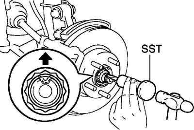
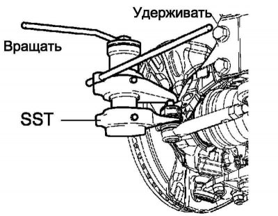
Pic. 3.99. Disconnection of the deformed part of the flange of the front wheel hub nut
Using special tool 09930-00010 and a hammer, bend the deformed part of the collar of the front wheel hub nut (pic. 3.99).
Attention! Bend the deformed part of the shoulder completely, otherwise the threads on the drive may be damaged.
Loosen the front wheel hub nut while depressing the brake pedal.
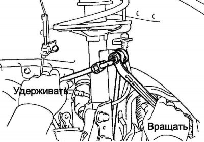
Pic. 3.100. Disconnecting the front anti-roll bar from the front suspension strut
Unscrew the nut, disconnect the front anti-roll bar from the front suspension shock absorber (pic. 3.100).
Note. If the ball joint pin turns with the nut, use a socket wrench (6 mm), to fix your finger.
Remove the speed sensor wire clamp.
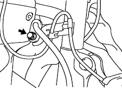
Pic. 3.101. Disconnecting the speed sensor wire clamp
Unscrew the bolt, disconnect the sensor wire and the front flexible hose No. 1 from the front suspension shock absorber strut (pic. 3.101).
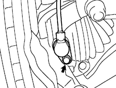
Pic. 3.102. Disconnecting the speed sensor from the steering knuckle
Remove the bolt, disconnect the speed sensor from the steering knuckle (pic. 3.102).
Remove the cotter pin and nut.
Pic. 3.103. Disconnection of steering draft from a rotary fist
Using special tool 09628-00011, disconnect the tie rod from the steering knuckle (pic. 3.103).
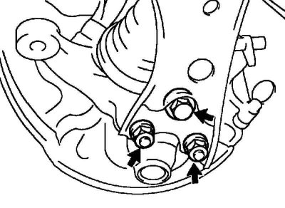
Pic. 3.104. Disconnecting suspension arm No. 1 from the lower ball joint
Remove the bolt and 2 nuts, and separate the #1 suspension arm from the lower ball joint (pic. 3.104).
Using a nylon hammer, disconnect the front wheel drive assembly from the wheel hub.
Attention! Be careful not to damage the boot and speed sensor rotor.
Remove the front wheel drive assembly.
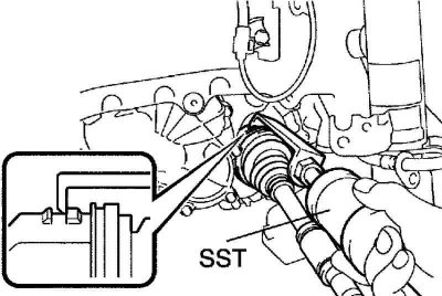
Pic. 3.105. Removing the front wheel drive assembly
Using the special tool 09520-01010, 09520-24010, remove the front wheel drive assembly (pic. 3.105).
Attention! Be careful not to damage the seal.
Turn away a bolt and remove the right drive of a forward wheel in gathering.
Lock the front wheel hub.
Attention! The hub bearing can be damaged by the weight of the vehicle when the vehicle is moved with the drive shaft removed.
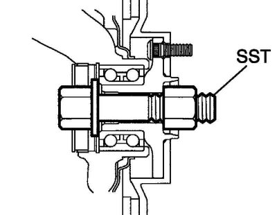
Pic. 3.106. Fixing the hub relative to the steering knuckle using a special tool
Therefore, if it is necessary to move the vehicle on wheels, first fix the hub relative to the steering knuckle using the special tool 09608-16042 (pic. 3.106).
Check of a drive of a forward wheel assy
Check the front wheel drive assembly.
Make sure there is no significant play in the outer hinge.
Make sure that the inner hinge moves smoothly in the axial direction.
Ensure that there is no significant radial play in the inner joint
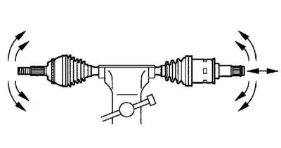
Pic. 3.107. The scheme of check of a drive of a forward wheel assy
Make sure protective covers are not damaged (pic. 3.107).
Attention! Move the drive shaft while keeping it horizontal.
Front wheel drive disassembly

Pic. 3.108. Removal of a collar of a cover of the internal hinge
Using a screwdriver, remove the inner hinge boot clamps (pic. 3.108).
Remove the inner hinge cover.
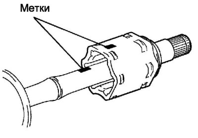
Pic. 3.109. Application of mounting marks on the tripod, shaft and hinge body
Put mounting marks on tripod, shaft and hinge housing (pic. 3.109).
Attention! Do not make marks with a core or chisel.
Remove the inboard joint housing from the shaft.
Using a circlip expander, remove the shaft circlip.
Put mounting marks on the tripod and shaft.
Attention! Do not make marks with a core or chisel.
Pic. 3.110. Removing the tripod assembly from the shaft
Using a brass rod and hammer, remove the tripod assembly from the shaft (pic. 3.110).
Attention! Do not hit the rollers.
Removal of a damper of the left drive of a forward wheel (Manual Transmission)
Using a screwdriver, remove the damper clamp.
Remove the front wheel drive damper.
Using a screwdriver, remove the damper clamp.
Remove the front wheel drive damper (except 1mz-fe engine).
Using a screwdriver, remove the outer hinge boot clamps.
Remove the protective cover of the outer hinge
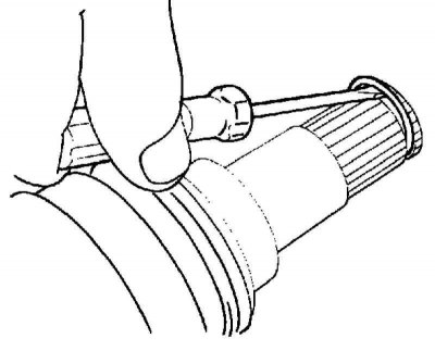
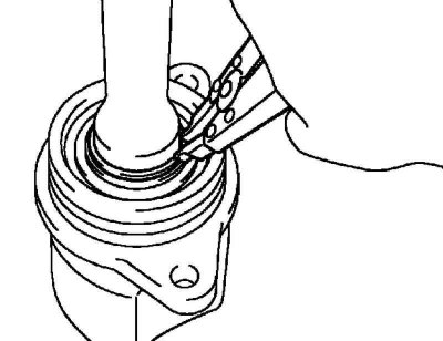
Pic. 3.111. Removal of a lock ring of a drive of a forward wheel
Remove the front wheel drive retaining ring. Using a screwdriver, remove the retaining ring (pic. 3.111).
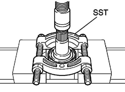
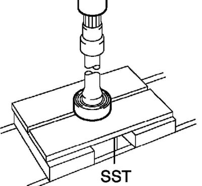
Pic. 3.112. Removal of the left dustproof ring of a drive of a forward wheel
Using special tool 09950-00020 and a press, remove the left front wheel drive dust ring (pic. 3.112).
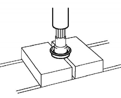
Pic. 3.113. Removal of the right dustproof ring of a drive of a forward wheel
Using a press, remove the right front wheel drive dust ring (pic. 3.113).
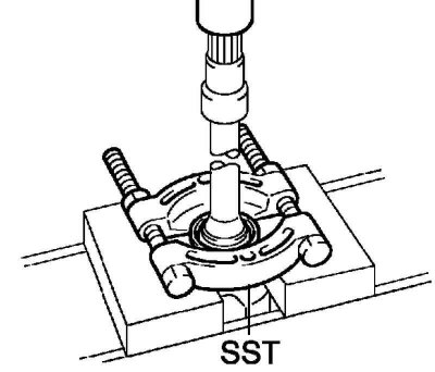
Pic. 3.114. Removal of a dustproof ring of a drive of a forward wheel
Using tool 09950-00020 and a press, remove the front wheel drive dust ring.
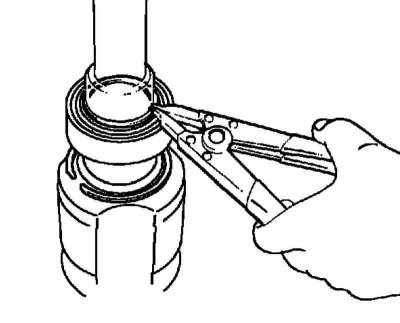
Pic. 3.115. Removing the right retaining ring
Using circlip pliers, remove the right circlip (pic. 3.115).
Pic. 3.116. Removing the front wheel drive bearing
Using special tool 09527-10011 and a press, remove the front wheel drive bearing (pic. 3.116).
Installation
Install the front wheel drive bearing
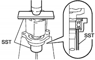
Pic. 3.117. Installing a new front wheel drive bearing
Using special tool 09527-30010, 09527-10011 and a press, install a new front wheel drive bearing (pic. 3.117).
Pic. 3.118. Installing a new right retaining ring
Using a circlip expander, install a new right circlip (pic. 3.118).
Install the front wheel drive dust cover.
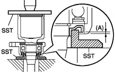
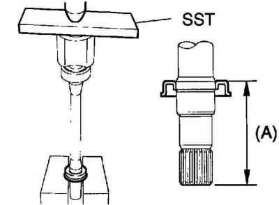
Pic. 3.119. Installation diagram of a new front wheel drive dust cover
Using tool 09527-10011, 09726-40010 and a press, install a new front wheel drive dust boot. The distance from the end of the drive shaft to the dust ring, as shown in Figure 3.119, must be correct.
Distance A: 0±1.0 mm.
Install the right front wheel drive dust ring
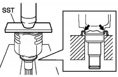
Pic. 3.120. Installation diagram of the new right front wheel drive ring
Using tool 09527-10011 and a press, install a new right front wheel drive dust ring. The distance from the end of the drive shaft to the dust protection ring, as shown in Figure 3.120, must be correct.
Size A: 91-92 mm.
Install the left front wheel drive dust ring.
Pic. 3.121. Installation diagram of the new right front wheel drive ring
Using tool 09527-10011 and a press, install a new left front wheel drive dust ring (pic. 3.121).
Install a new left front wheel drive retaining ring.
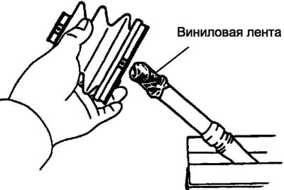
Pic. 3.122. Installing the protective cover of the outer hinge
Install the protective cover of the outer hinge (pic. 3.122).
Note. Before installing the boots, wrap the spline of the drive shaft with adhesive tape so as not to damage the boots.
Amount of lubricant:
- CD-FTV: 105–125
- 3ZZ-FE, 1ZZ-FE: 152-162g
Temporarily install a new outer joint boot with 2 yokes on the drive shaft.
Fill the inboard joint housing and boot with grease.
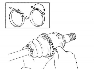
Pic. 3.123. Installation of a collar of a protective cover of the external hinge
Establish a collar of a protective cover of the external hinge (pic. 3.123).
Install the drive shaft in a soft vice.
Attach the 2 outer hinge protective boot clamps to the boot.
Install special tool 09521-24010 on the larger outer hinge boot collar.
Attention! The position of the right clamp of the protective cover of the outer hinge and the left clamp of the protective cover of the outer hinge in the grooves of the cover during tightening should be as shown in Figure 3.123.
Gap: 0.8mm or more.
Tighten the special tool screw until the large clamp is compressed.
Attention! Do not over-tighten the special tool screw.
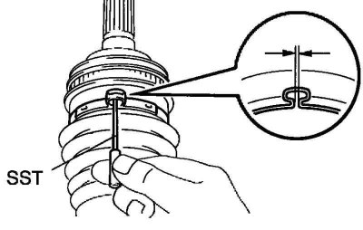
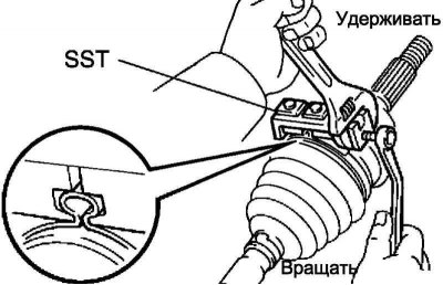
Pic. 3.124. Large clamp gap adjustment
Using special tool 09240-00020, adjust the gap of the large clamp (pic. 3.124).
Gap: 0.8mm or less.
Install the small collar of the outer hinge boot in the same way.
Install the front wheel drive damper (Manual Transmission).
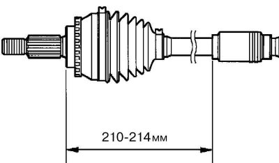
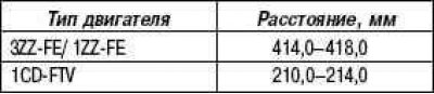
Pic. 3.125. Front wheel drive damper installation distance
Make sure the front wheel drive damper is in the shaft groove (pic. 3.125).
It is necessary to maintain the distance given below.
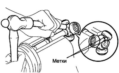
Install the front wheel drive inner joint
Position the tripod with the lead-in chamfer to the outer joint shaft.
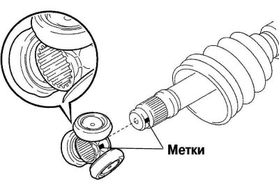
Pic. 3.126. Alignment of mounting marks applied before disassembly before installing the inner hinge
Align the mounting marks made before disassembly (pic. 3.126).
Using a brass rod and hammer, install the tripod onto the outer joint shaft.
Attention! Do not hit the rollers.
Using a circlip expander, install a new circlip onto the shaft.
Fill the inboard joint housing and boot with grease.

Install the inner joint boot on the shaft.
Establish a collar of a cover of the internal hinge
Pic. 3.127. Fixing the clamps of the inner hinge cover with a screwdriver
Bend the strap and secure the inner hinge boot clamps with a screwdriver (pic. 3.127).
Check the front wheel drive.
Make sure there is no significant play in the outer hinge.
(Make sure that the inner hinge moves smoothly in the axial direction.
Make sure there is no significant radial play in the inner joint.
Make sure the protective covers are not damaged.
Attention! Move the drive shaft while keeping it horizontal.
Make sure that the boots are in the grooves of the shaft.
Make sure the boots are not stretched or compressed when the drive shaft is in the free position.