A) Remove the center panel.
b) Turn on the ignition.
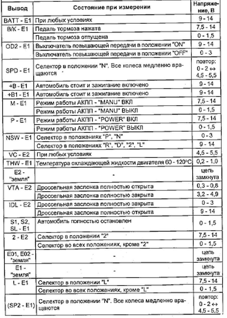
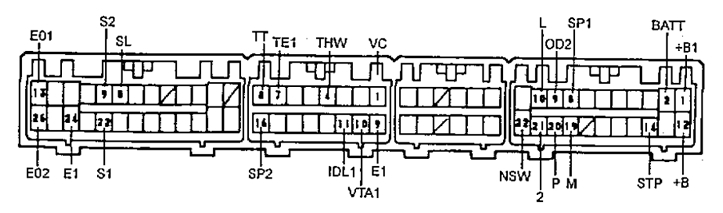
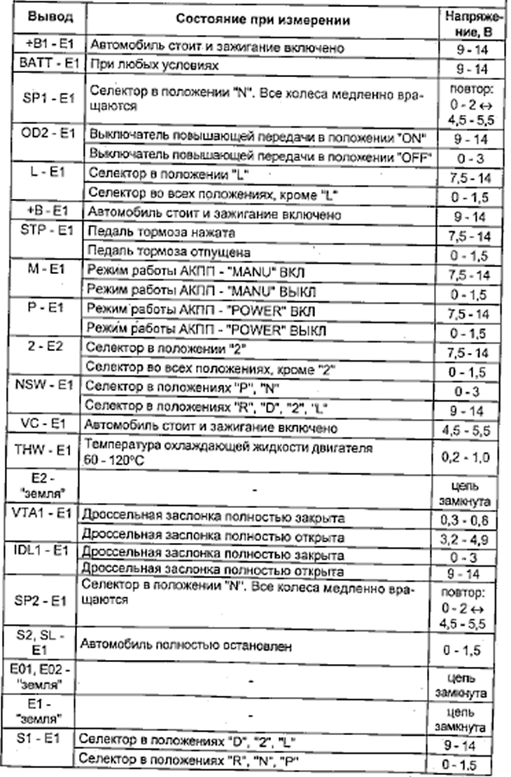
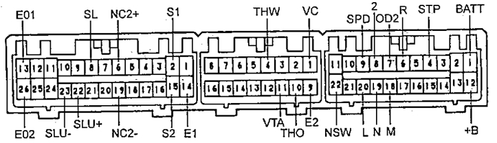
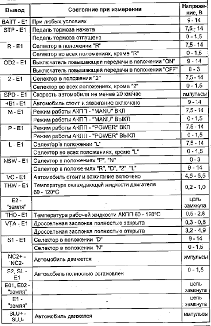
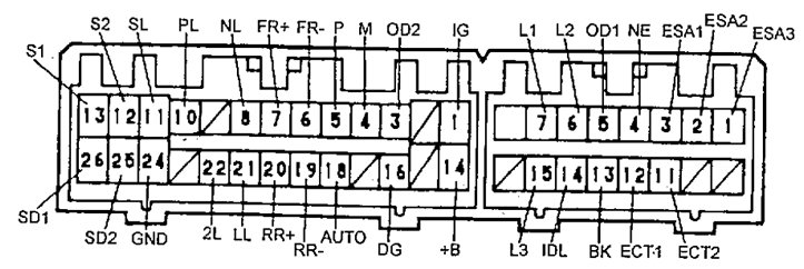
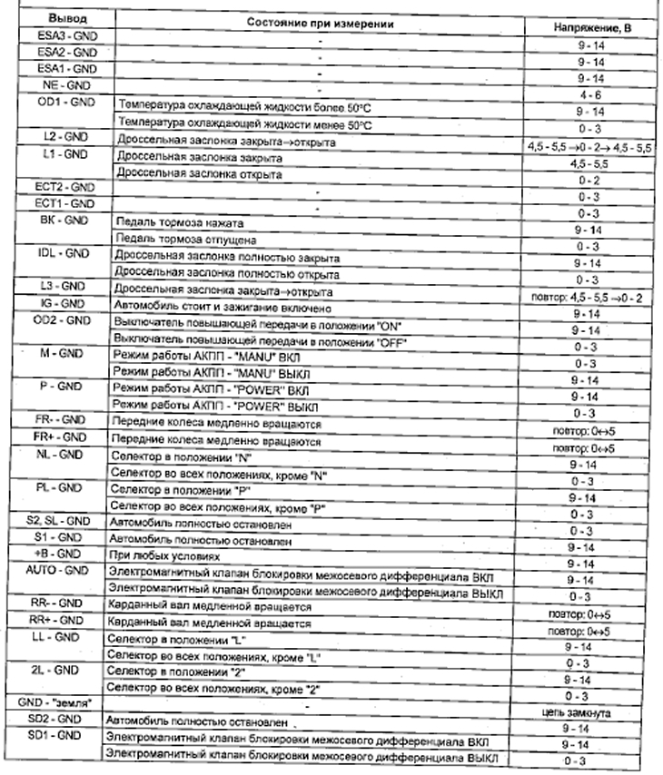
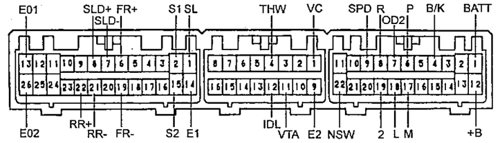
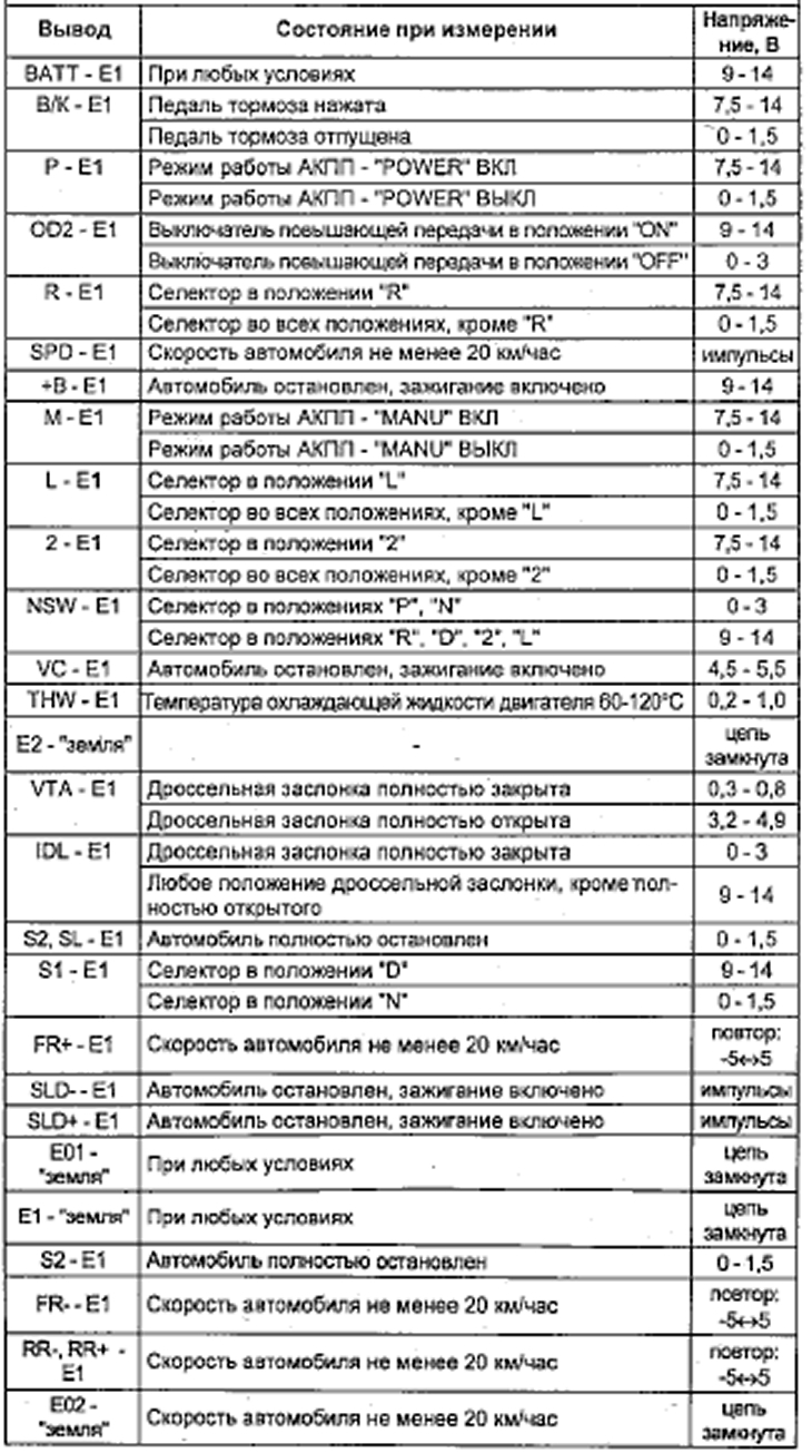
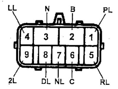
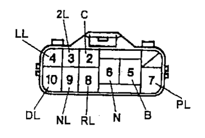
V) Measure the voltage at each terminal of the control unit connector for the automatic transmission and the engine (see table "Voltage at the terminals of the automatic transmission control unit connector").
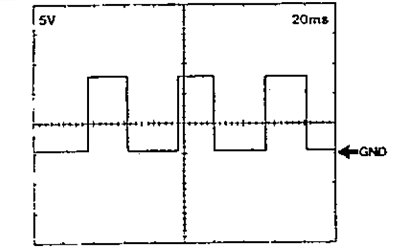
Note (for models from 1994): waveform between pins "SPD" And "EG when the car is moving at a speed of more than 20 km / h.
Note: The higher the vehicle speed, the higher the frequency of the pulses generated by the speed sensor.
(A245E) waveform between pins "SLU-" And "SLU+" when the torque converter lock is off.
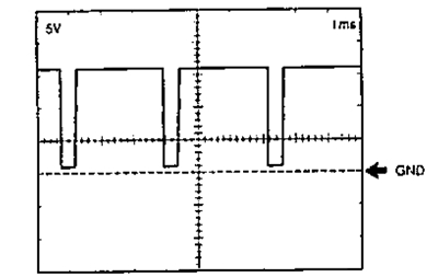
(A245E) waveform between pins "NC2+" And "NC2-" when the car is moving at a speed of about 60 km / h on the range "D".
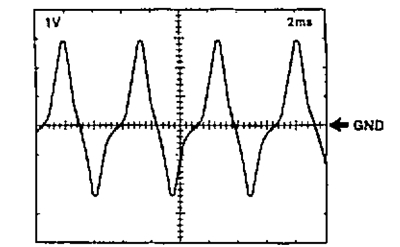
(A540E) waveform between pins "SLD+" And "E1", "SLD-" And "E1".
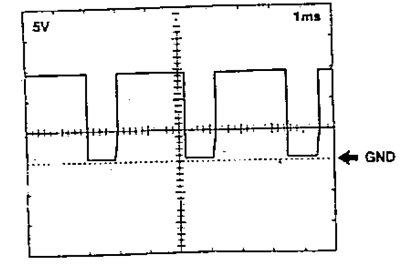
Table. Voltage at the terminals of the automatic transmission control unit connector (A241E, A245E) (5A-FE, 4S-FE)
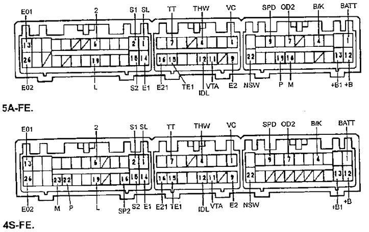
(): Only for 4S-FE.
2. Check solenoid valves.
A) Disconnect the solenoid valve block connector.
A245E until 1994, A241E
A540H
A245E since 1994
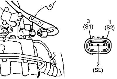
b) Measure resistance between leads "31", "S2", "SL" And "earth".
- Rated resistance - 10-16 0m
V) (A245E)
Measure resistance between leads "3" And "7" solenoid valve connector.
- Rated resistance - 3.5-3.9 ohms
If the resistance is not as specified, check the torque converter lock-up quality control solenoid valve circuit.
V) Apply battery voltage to each terminal. A click indicates that the solenoid valves are working.
3. (A540N until 1994).
Check the center differential lock solenoid valves.
Note: Foreign material in the solenoid valve may cause it to malfunction.
A) Disconnect the automatic transmission electronic control unit connector and apply battery voltage to the terminals "24"-"26" (solenoid valve No. 1) And "24"-"25" (solenoid valve No. 2). Make sure the solenoid valves are working.
Table. Voltage at the terminals of the automatic transmission control unit connector (A241E, A245E until 1994) (4A-FE)
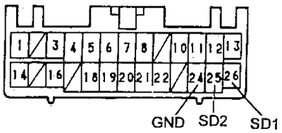
b) Check resistance between terminals "24"-"26" (solenoid valve No. 1) And "24"-"25" (solenoid valve No. 2) connector of the automatic transmission electronic control unit.
- Rated resistance - 10-16 Ohm
V) Check the resistance between each terminal of the center differential lock solenoid valve connector and "earth".
- Rated resistance - 10-16 Ohm
4. (A540N since 1994)
Check the center differential lock solenoid valve.
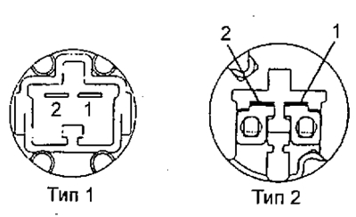
A) Connect the positive terminal of the battery through a 21 W lamp to the terminal "1" valve connector and negative battery terminal to terminal "2", the valve must move.
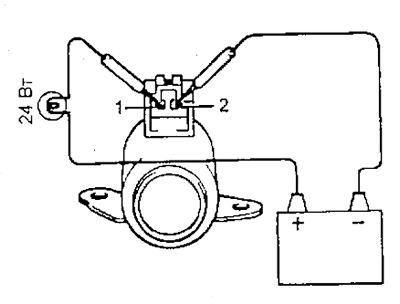
b) Measure the resistance between the valve connector terminals.
- Rated resistance - 5.1-5.5 0m
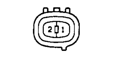
5. (A245E since 1994)
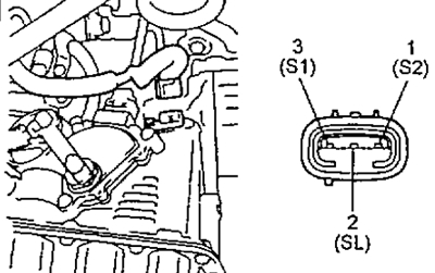
Check the torque converter lock-up quality control solenoid valve.
A) Connect the positive terminal of the battery through a 21 W lamp to the terminal "2" valve connector and negative battery terminal to terminal "1", the valve must move.
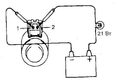
b) Measure the resistance between the valve connector terminals.
- Rated resistance - 3.5-3.9 ohms
Table. Voltage at the terminals of the automatic transmission control unit connector (A245E since 1994)
6. (A245E until 1994)
Check speed sensor #2.
A) Move the selector to position "N" and jack up the front wheels.
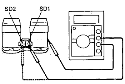
b) Disconnect the sensor connector and check for pulses on the outputs "SP2" And "GND" sensor connector when the wheel is rotated.
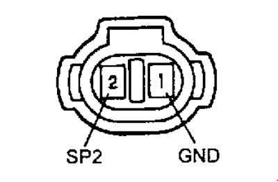
Table. Voltage at the terminals of the automatic transmission control unit connector (A540N until 1994)
V) Remove the sensor. Bringing the magnet to the end of the sensor, make sure that the circuit between the terminals of the sensor connector is closed when the magnet is brought up, and open if there is no magnet.
7. (A245E since 1994)
Check speed sensor #2.
Measure the resistance between the sensor connector pins.
- Rated resistance - 560-680 Ohm
If the measured resistance differs from the nominal, then replace the sensor.
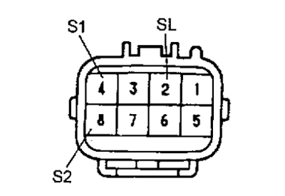
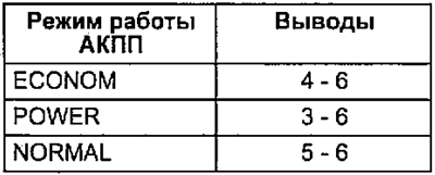
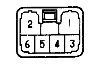
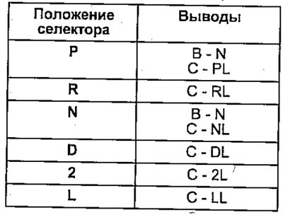
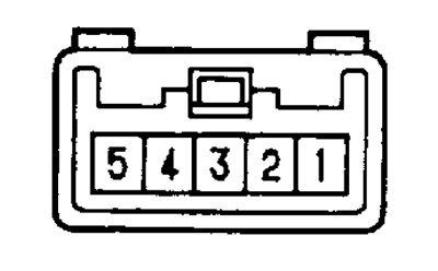
8. Check the automatic transmission mode selection switch.
Check the continuity between the terminals of the automatic transmission mode selection switch connector indicated in the table.
Note: to conclusions "1" And "2" connector, the backlight is connected.
9. Check the overdrive switch.
With pin-to-pin conduction boost mode enabled "2" And "4" should not be, 5; when off - conductivity should be, otherwise - replace the switch.
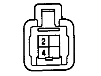
Table. Voltage at the terminals of the automatic transmission control unit connector (A540N since 1994)
10. Check the start inhibit switch.
Check the continuity between the connector pins indicated in the table.
A241E
A245E, A540H
If there is no continuity between the indicated terminals, replace the start inhibit switch.
11. Check continuity between terminals "1" And "2" brake light switch connector.
When the pedal is pressed, the conductivity should be, when the pedal is released, there should not be any conductivity. Otherwise, replace the brake light switch.
12. Check Speed Sensor #1 (see chapter "Body electrical equipment").
13. (A540N)
Check speed sensors.
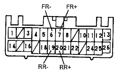
A) Measure resistance between leads "6"-"7" (front wheel speed sensor) And "19"-"20" (rear wheel speed sensor) connector of the automatic transmission electronic control unit.
- Rated resistance - 560-740 Ohm
b) Measure resistance between leads "1" And "2" sensor connector.
- Rated resistance - 560-740 Ohm
14. (A540N)
Make sure the position "ON", there is conduction between the terminals "1", "2" And "5" inter-axle differential lock switch connector. Otherwise, replace the switch.
Note: to conclusions "3" And "4" backlight connected.
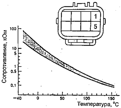
15. (A245E since 1994)
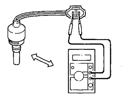
Check the automatic transmission fluid temperature sensor.
Measure resistance between leads "1" And "5" solenoid valve connector.
If the resistance does not change as shown in the figure, then replace the sensor.