A) Remove the center panel.
b) Turn on the ignition.
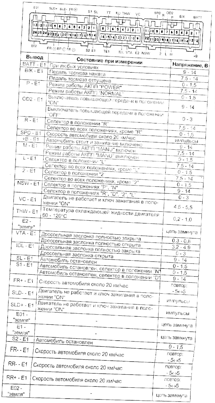
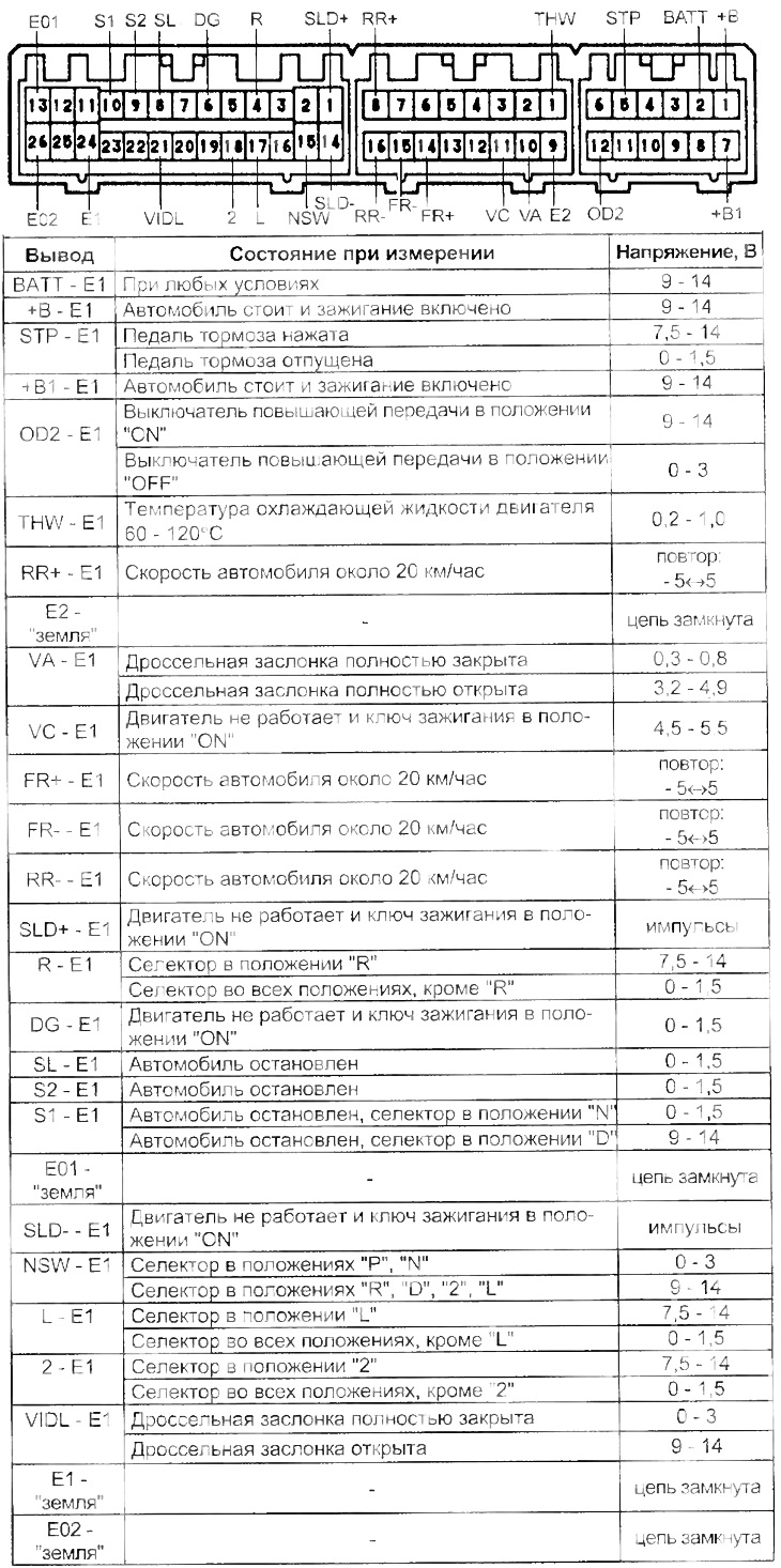
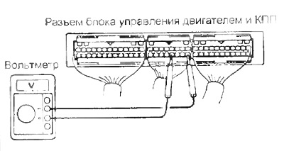
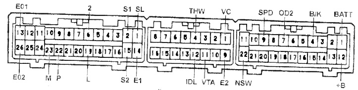
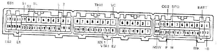
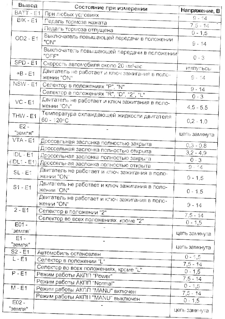
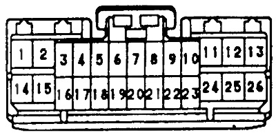
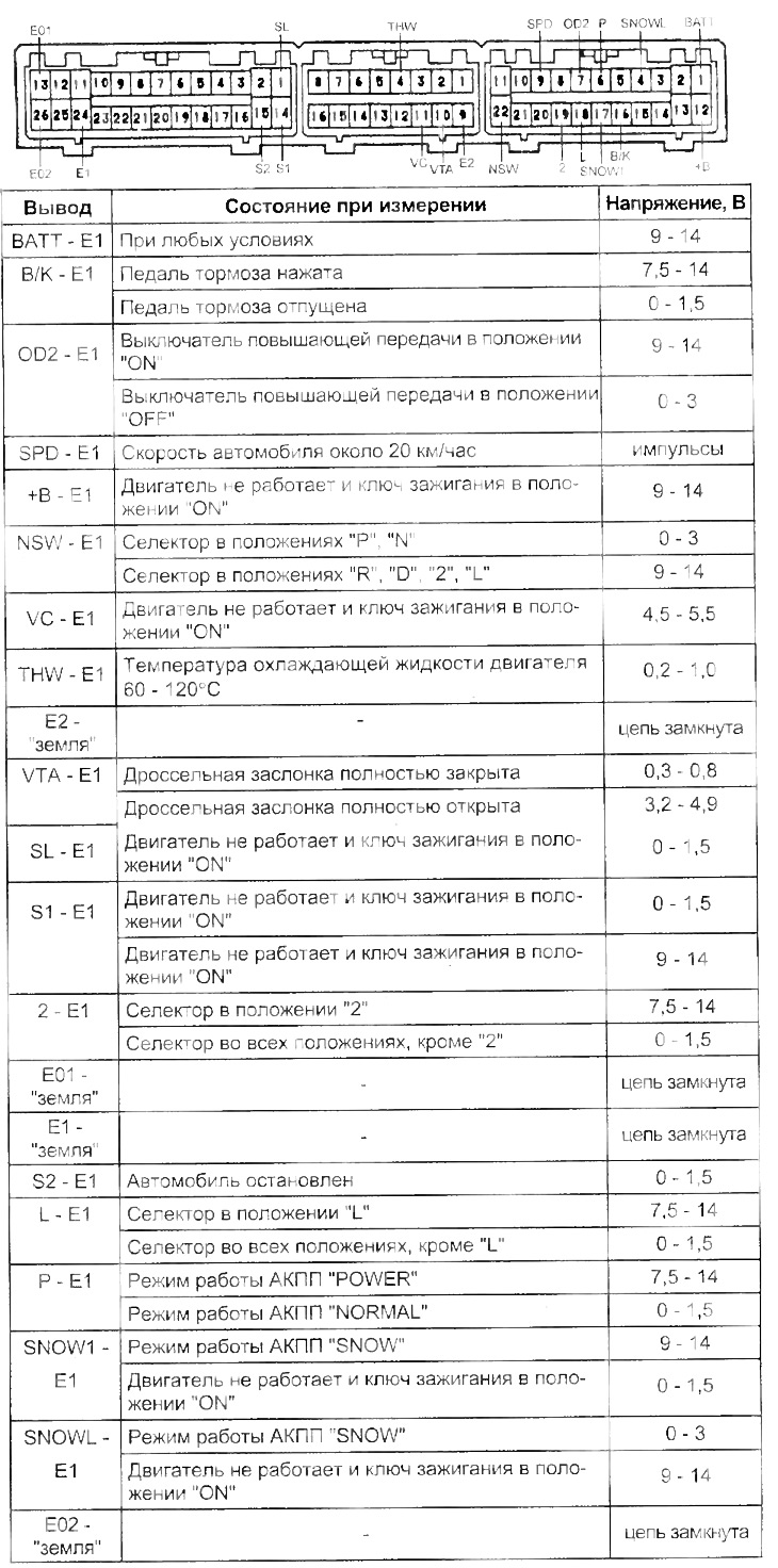
V) Measure the voltage at each terminal of the automatic transmission and engine control unit connector (see table "Voltage at the terminals of the automatic transmission control unit connector").
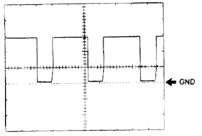
Waveform Between Pins "SPD" And "E1" at a speed of at least 20 km/h. Value of division (cells) 5 V and 20 ms.
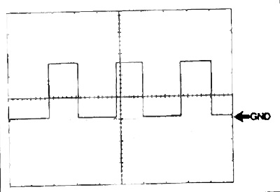
Waveform Between Pins "SLD+" And "E1" And "SLD-" and PEG\ Division value (cells) 5 V and 1 ms. Ignition key in the ON position.
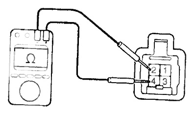
2. Check the start inhibit switch.
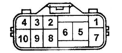
Check for continuity between the connector pins shown in the table.
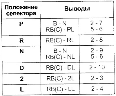
(): for A540H.
If there is no continuity between the indicated terminals, replace the start inhibit switch.
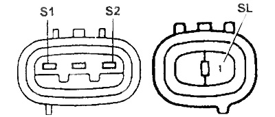
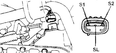
3. Check solenoid valves.
A) Disconnect the solenoid valve connector.
b) Measure resistance between leads "S1", "S2", "SL" And "earth".
- Rated resistance - 11 - 15 Ohm
А140Н
A540N
V) Apply battery voltage to each terminal. A click indicates that the solenoid valves are working.
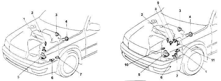
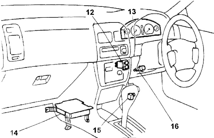
The location of the elements of the electrical part of the gearbox control system.
1 - torque converter blocking solenoid valve,
2 - engine coolant temperature sensor,
3 - throttle position sensor,
4 - diagnostic connector,
5 - engine start prohibition switch,
6 - solenoid valve No. 1,
7 - solenoid valve No. 2,
8 - rear output shaft speed sensor,
9 - solenoid valve for locking the center differential,
10 - automatic transmission fluid overheating sensor,
11 - front output shaft speed sensor,
12 - automatic transmission mode selection switch,
13 - vehicle speed sensor (instrument cluster),
14 - automatic transmission electronic control unit,
15 - overdrive switch (O/D),
16 - brake light switch.
4. Check continuity between terminals "2" And "4" overdrive switch connector. When the overdrive mode is on, there should be no conductivity, when it is off, there should be conductivity. Otherwise, replace the switch.
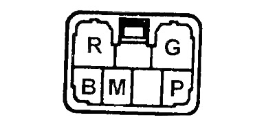
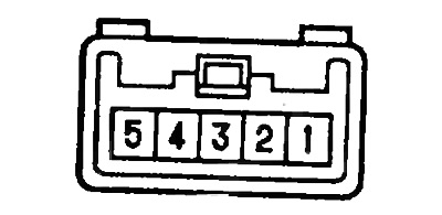
5. Check up conductivity between conclusions of a socket of the switch of a choice of an automatic mode of operation, as it is specified in the table.
Except A140E (since May 1996)
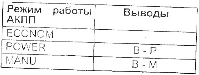
Note: to conclusions "R" And "G" switch light is connected.
Except A140E (smaya 1996)
A140E (since May 1996)
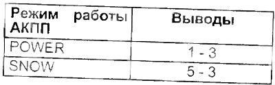
Note: to conclusions "2" And "4" switch light is connected.
A140E (since May 1996)
6. Check the engine coolant temperature sensor.
Measure the resistance between the sensor connector pins. Replace the sensor if the resistance is not within the limits shown in the figure.
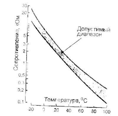
Table. Voltage at the terminals of the automatic transmission control unit connector.
A140E.
Models without traction control (TRC)
Models with traction control (TRC)
(): for models without traction control (TRC).
7. (A540N)
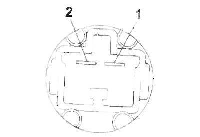
Check the center differential lock solenoid valve
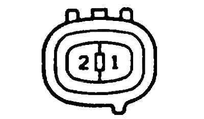
A) Connect the positive battery terminal through a 24W lamp to the terminal "1" valve connector and negative battery terminal to terminal "2", the valve must move.
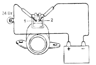
b) Check resistance between terminals "1" And "2" solenoid valve connector
- Rated resistance - 5.1 - 5.5 Ohm
8. (A540N)
Check speed sensors (front and rear output shaft).
A) Disconnect the automatic transmission electronic control unit connector and check between connector pins 6 -19 (front output shaft speed sensor) and 21 - 22 (rear output shaft speed sensor) resistance.
- Rated resistance - 560 - 680 Ohm
b) Disconnect the sensor connectors and remove the gearbox output speed sensors.
V) Using an ohmmeter, check the resistance between the terminals of the connectors
- Rated resistance - 560 - 680 Ohm
9. (A540H)
Check the continuity between the terminal and the connector housing of the automatic transmission fluid overheating sensor when the temperature of the fluid changes as shown in the figure.
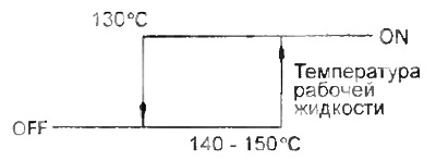
If the conductivity is not as specified, replace the sensor.
Table. Voltage at the terminals of the automatic transmission control unit connector.
A140E (since May 1996)
10. Check the brake light switch.
Check continuity between terminals "1" And "2", brake light switch connector.
When the pedal is pressed, the conductivity should be, when the pedal is released, there should not be any conductivity. Otherwise, replace the brake light switch.
Table. Voltage at the terminals of the automatic transmission control unit connector (continuation). A540N (3S-FE).