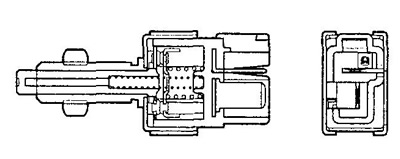
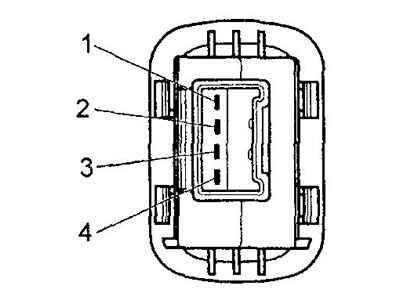
Checking the engine start inhibit switch
Check for continuity between the connector pins shown in the table.
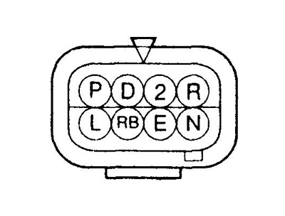 | 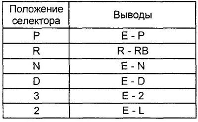 |
If there is no continuity between the indicated terminals, replace the start inhibit switch.
Checking the input shaft speed sensor and the output shaft speed sensor
Sensors can only be checked with an oscilloscope. If the sensors are faulty, fault codes will be displayed (37, 42). You can check the sensor signals at the corresponding terminals of the automatic transmission electronic control unit.
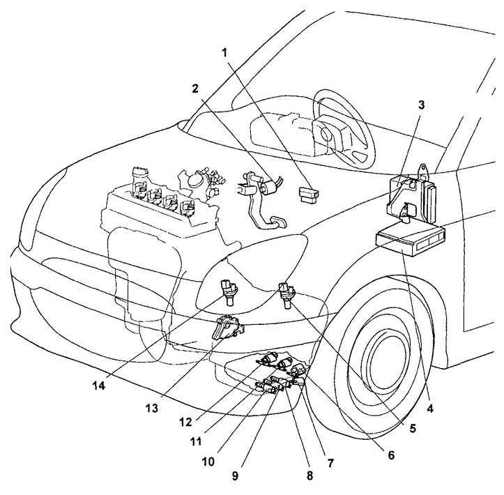
Location of elements of the electrical control system (models without gearshift mode on the steering wheel).
1 - diagnostic connector,
2 - brake light switch,
3 - electronic engine control unit,
4 - automatic transmission electronic control unit,
5 - output shaft speed sensor,
6 - solenoid valve for partial blocking of the torque converter (LUCR),
7 - working fluid temperature sensor (automatic transmission),
8 - solenoid valve No. 3,
9 - solenoid valve No. 1,
10 - solenoid valve No. 2,
11 - torque converter blocking solenoid valve (LUCC),
12 - switching solenoid valve (SOLR),
13 - engine start prohibition switch,
14 - input shaft speed sensor.
Checking the manual shift switch
1. Remove the steering wheel together with the airbag module.
Attention:
- Disconnect the airbag module no earlier than 60 seconds after disconnecting the wire from the negative battery terminal.
- When removing, refer to the relevant chapter "Safety system (SRS) ".
2. With the switch button pressed, make sure there is continuity between the terminals "1" (E) - "2" (SPT) manual shift switch connector.
Checking the gear switches on the steering wheel
1. Remove the steering wheel together with the airbag module.
Attention:
- - Disconnect the airbag module no earlier than 60 seconds after disconnecting the wire from the negative battery terminal.
- - When removing, refer to the relevant chapter "Safety system (SRS) ".
2. With the upshift switch button depressed, check for continuity between the terminals "SIFTU" - "E" upshift switch connector.
3. With the downshift switch button depressed, check for continuity between the terminals "SIFTD" - "E" downshift switch connector.
Checking the solenoid valves
1. Disconnect the solenoid valve connector from the transmission.
2. Measure the resistance between the terminal "1" (SOLR), conclusion "2" (LUCR) and mass.
- Rated resistance - 14 -18 Ohm
3. Connect the positive battery terminal to the terminal "1" (SOLR), and negative - to the ground, with a working valve, a click should sound. Repeat procedure to withdraw "2" (LUCR).
4. Measure the resistance between the terminal "3" (LUCC) solenoid valve connector and ground.
- Rated resistance - 11 - 13 Ohm
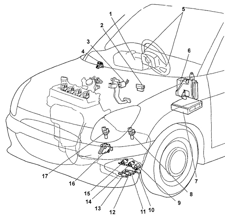
Location of elements of the electrical control system (models with gearshift mode on the steering wheel).
1 - gear engaged indicator,
2 - diagnostic connector,
3 - brake light switch,
4 - manual shift mode switch,
5 - gear selector on the steering wheel,
6 - electronic engine control unit,
7 - automatic transmission electronic control unit,
8 - output shaft speed sensor,
9 - solenoid valve for partial blocking of the torque converter (LUCR),
10 - automatic transmission fluid temperature sensor,
11 - solenoid valve No. 3,
12 - solenoid valve No. 1,
13 - solenoid valve No. 2,
14 - torque converter blocking solenoid valve (LUCC),
15 - switching solenoid valve (SOLR),
16 - engine start prohibition switch,
17 - input shaft speed sensor.
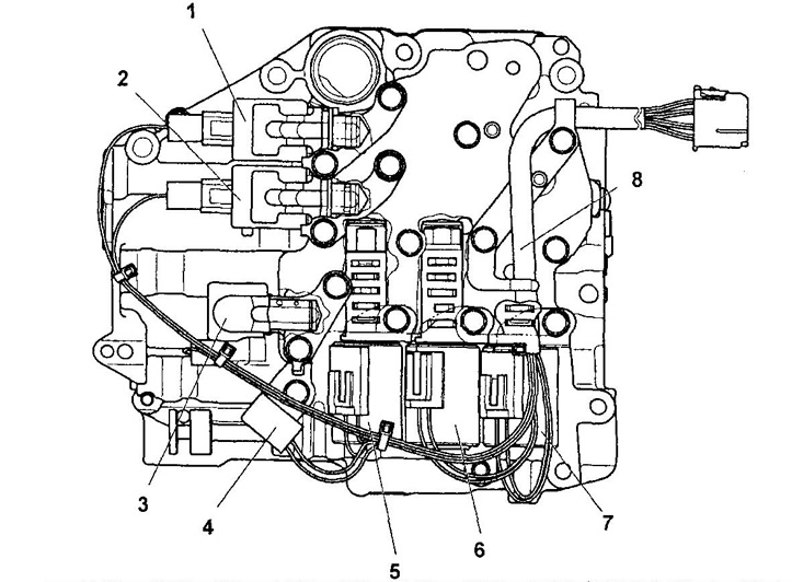
Location of solenoid valves.
1 - switching solenoid valve (SOLR),
2 - torque converter lock-up solenoid valve (LUCC),
3 - solenoid valve for partial blocking of the torque converter (LUCR),
4 - automatic transmission fluid temperature sensor,
5 - solenoid valve No. 3,
6 - solenoid valve No. 1,
7 - solenoid valve No. 2,
8 - wiring harness for solenoid valves.
5. Connect the positive battery terminal to the terminal "3" (LUCC), and negative - to the ground, with a working valve, a click should sound.
6. Measure the resistance between the solenoid valve connector pins "5" (OTMR) And "9" (E).
Rated resistance:
- at 0°C - 5-6 Ohm
- at a temperature of 140°C - 70 - 74 Ohm
7. Check solenoid valves "№ 1", №2, №3.
A) Measure the resistance between the solenoid valve connector pins "6" (B1+) And "10" (IN 1-).
b) Measure the resistance between the solenoid valve connector pins "8" (С2+) And "12" (C2-).
V) Measure the resistance between the solenoid valve connector pins "7" (SZV2+) And "11" (SZV2-).
- Rated resistance - 5.0 - 5.6 ohms
10. Check for continuity between each solenoid valve connector pin and the corresponding solenoid valve connector pin (see fig. "Checking the Solenoid Harness").
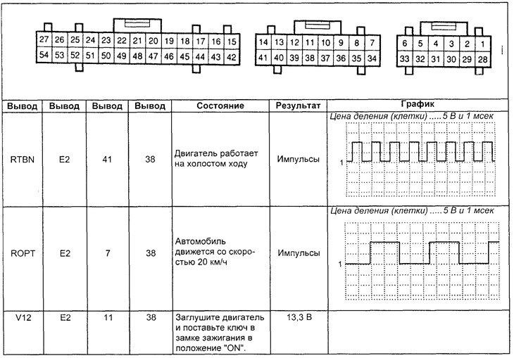
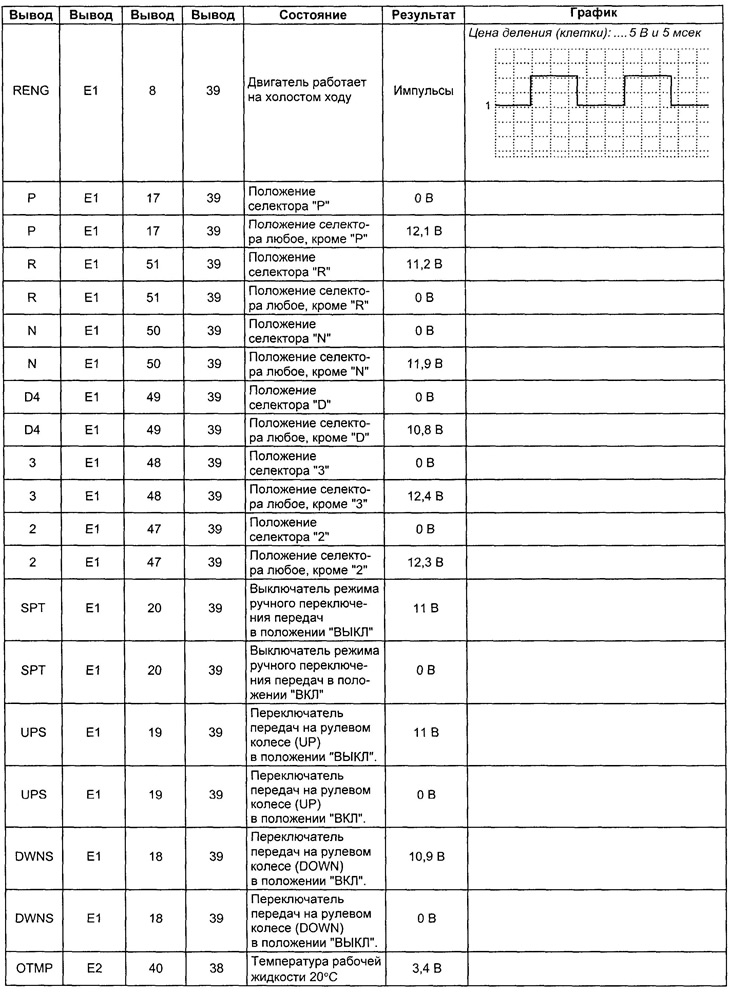
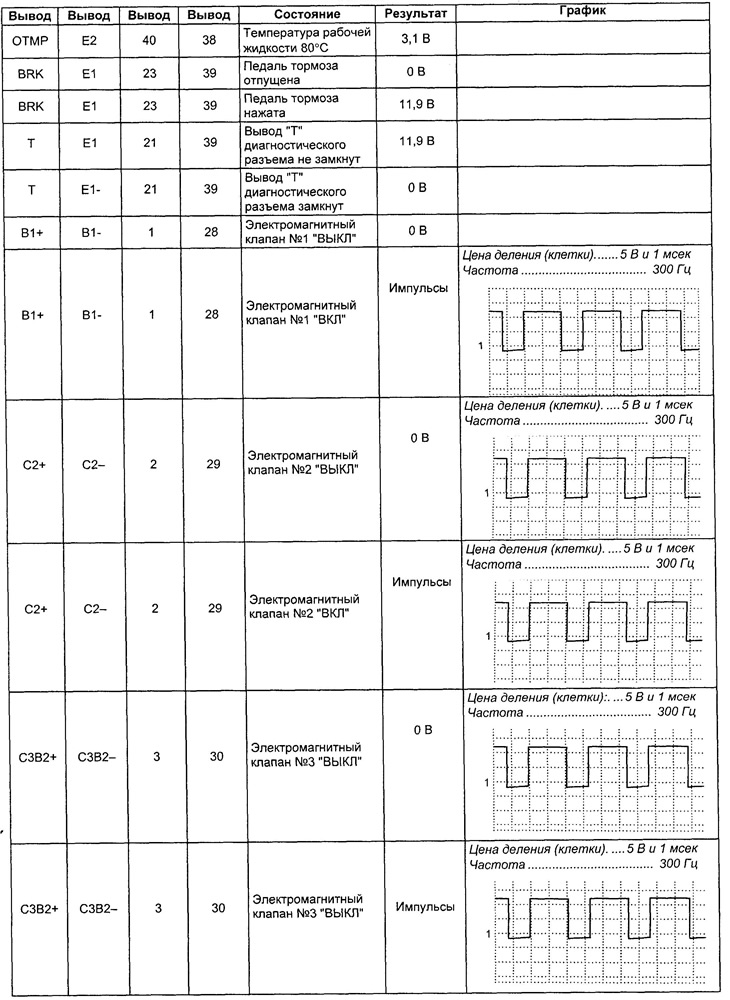
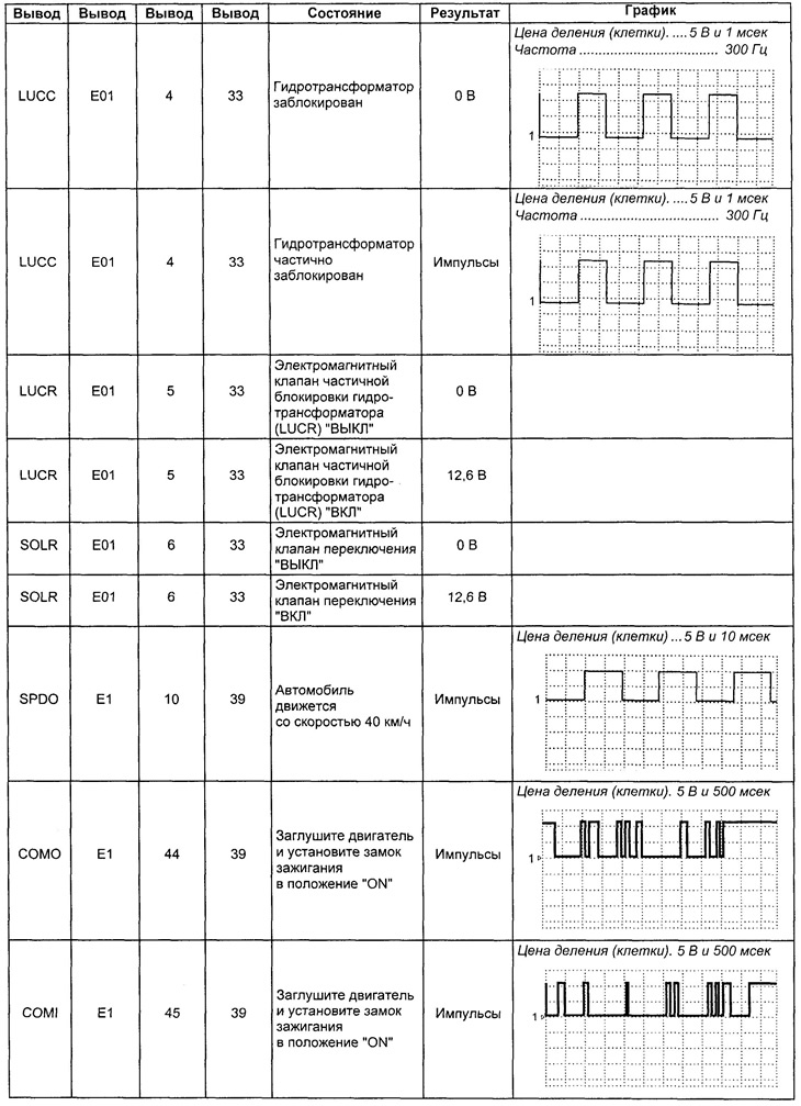
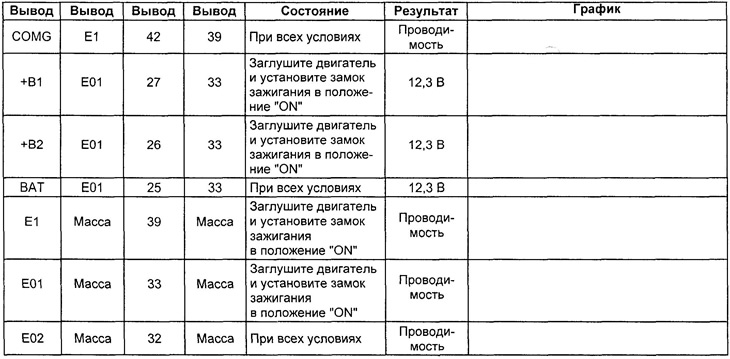
11. Check the voltage at the terminals of the automatic transmission control unit connector.
A) Turn on the ignition.
b) Measure the voltage at each terminal of the automatic transmission and engine control unit connector (see table "Voltage at the terminals of the automatic transmission control unit connector").
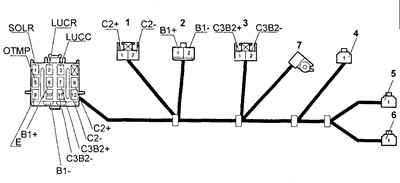
Checking the solenoid valve harness.
1 - solenoid valve No. 2,
2 - solenoid valve No. 1,
3 - solenoid valve No. 3,
4 - solenoid valve for partial blocking of the torque converter (LUCR),
5 - torque converter blocking solenoid valve (LUCC),
6 - switching solenoid valve (SOLR).
Table. Voltage at the terminals of the automatic transmission control unit connector.
Checking the brake light switch
Check for continuity between the brake light switch connector terminals.
Conductivity between pins:
- the brake pedal is pressed - there is conductivity
- brake pedal released - no continuity