
Examination
Attention! See the warnings at the beginning of the Section Check of serviceability of functioning and replacement of the breaker of indexes of turns / alarm system and the switch of the last.
1. One horn is placed behind the front grille in the space between the right headlight radiator. An additional horn is located symmetrically with respect to the first to the left of the radiator.
2. Disconnect the electrical wiring from the horn and apply battery voltage to one of its terminals. Ground the other terminal (use jumper wires). If the horn does not beep, replace it.
3. If the horn works properly, check the correctness of the voltage supply to the terminals of the horn connector when the horn button is pressed. If power is being applied properly, evaluate the quality of the assembly's ground connection.
4. If the power supply is interrupted, check the status of the relevant relay (see Section Relay - general information and function check). Please note that 4-pin assemblies are usually used as horns, or 3-terminal relays grounded through the case.
5. If the relay is in order, check the correctness of the voltage supply to its power and control circuits. If at least one of the circuits is not powered, evaluate the condition of the corresponding wiring between the relay and the mounting block.
6. If power is properly supplied to both relay circuits, press the horn button and check the grounding of the circuit section between the button and the relay. If there is no continuity to ground, check the circuit for an open. If there is no open, replace the horn switch.
7. If the grounding of the horn switch is not broken, check for an open or short circuit in the wiring in the section of the circuit between the relay and the switch.
Replacement
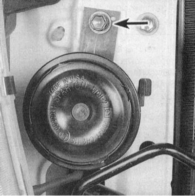
1. Disconnect the electrical wiring from the horn and unscrew the mounting bracket bolt (refer to accompanying illustration).
2. Unscrew the mounting bracket from the old horn and transfer it to the replacement one.
3. Installation is carried out in the reverse order.