
Attention! See the warnings at the beginning of the Section Check of serviceability of functioning and replacement of the breaker of indexes of turns / alarm system and the switch of the last.
1. Disconnect the negative cable from the battery.
Attention! If the stereo system installed in the car is equipped with a security code, before disconnecting the battery, make sure that you have the correct combination to activate the audio system!
2. Prying up, release the rear window heating switch from its seat in the instrument panel, disconnect the electrical wiring.
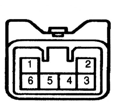
3. Make sure there is continuity between terminals 1 and 3 of the electrical wiring connector on the relay side (refer to accompanying illustration). If there is no continuity, replace the lamp.
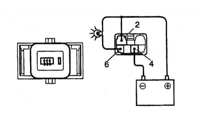
4. Using jumper wires, connect the positive pole of the battery to terminal No. 2 of the switch connector, the negative terminal No. 4. Next, through a 3.4 W probe lamp, connect the positive pole of the battery to terminal No. 6 (refer to accompanying illustration). Turn on the heater, the control lamp and test lamp should turn on for 12-18 minutes, then go out. A defective switch will need to be replaced.
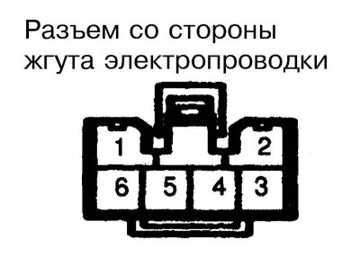
5. Disconnect the electrical wiring from the switch and check its connector from the side of the harness (refer to accompanying illustration):
- a. Between terminal No. 4 and ground, conduction must be constant;
- b. In the LOCK and ACC positions of the ignition key, there must be no voltage between terminal 2 and ground and between terminal 6 and ground;
- c. In the ON position of the key, the voltage between those specified in paragraph (b) pairs of terminals must take place;
- d. Jump between terminals 4 and 6 of the contact connector and make sure that the heating element of the rear window heater is working properly.
6. A defective switch must be replaced.
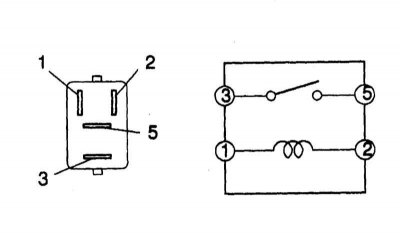
7. To check the correct operation of the heater relay (located in the cabin fuse box) make sure that continuity is always present between terminals 1 and 2 of the assembly (refer to accompanying illustration). Apply voltage between terminals 1 and 2 and check for continuity between terminals 3 and 5.
8. A defective relay must be replaced.