



Contents: Removal ↓ Installation ↓
Timing Drive Components (Part 1)
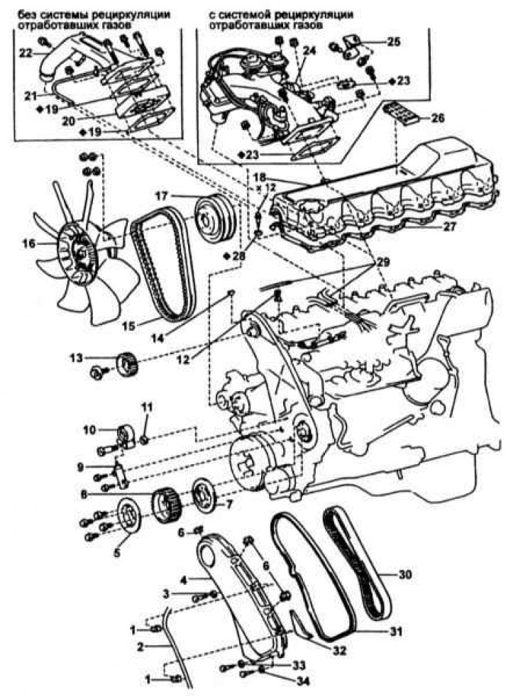
1 - Clamp; 2, 21 - Vacuum hose; 3, 28, 33, 34 - Sealing washer; 4 - Timing belt cover; 5 - Flange No.2; 6 - Clamp; 7 - Flange No.1; 8-Gear camshaft wheel; 9 - Timing belt tensioner; 10 - Tension roller; 11 - Flat washer; 12 - Clamp (models with ERG system); 13 - Camshaft gear wheel; 14 - Camshaft key; 15 - Drive belt; 16 - Fan; 17 - Water pump drive pulley; 18 - Cylinder head cover; 19, 23, 27, 31 - Gasket; 20 - Inlet heater; 22 - Inlet manifold; 24 - Assembling the intake manifold; 25 - EGR valve bracket; 26 - Heat shield; 29 - Vacuum hose (models with ERG system); 30 - Toothed belt; 32 - Protective screen
Timing Drive Components (Part 2)
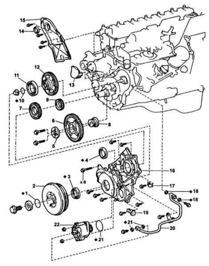
1 - Sealing ring; 2 - Crankshaft pulley; 3 - Front crankshaft oil seal; 4 - Fuel injection pump gear oil seal; 5 - Thrust plate; 6 - Intermediate gear; 7 - Oil pump drive gear; 8 - Intermediate gear shaft; 9 - Toothed wheel of fuel injection pump and timing drive; 10 - Sealing ring; 11 - Fuel injection pump gear bearing; 12 - Fuel injection pump gear; 13 - Heat shield No.2 of the cylinder block; 14 - Camshaft oil seal; 15 - Rear timing belt cover; 16 - Timing drive gear cover; 17 - Clamp; 18 - Gasket; 19 - Bracket; 20 - Oil pipe; 21 - Gasket; 22 - Vacuum pump
Removal
1. The timing drive components are shown in the illustrations above.
2. Remove the drive belt.
3. Remove the timing belt and camshaft sprockets
4. Remove the rear timing belt cover
5. Remove the two mounting bolts and remove the vacuum pump oil line
6. Remove the vacuum pump.
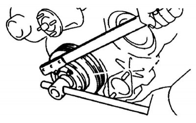
7. Block the crankshaft and unscrew the central bolt of its pulley (refer to the accompanying illustration).
8. Remove the spacer and use a puller to remove the crankshaft pulley.
9. Remove the 14 timing gear cover mounting bolts.
10. Measure the axial clearance of the intermediate gear and, if necessary, replace its thrust plate, shaft, or the gear itself.
11. Remove the oil pump drive gear using a puller.
12. Unscrew the two bolts, remove the thrust plate, gear wheel and its axle.
13. Lock the fuel injection pump gear, loosen its mounting nut and remove the gear.
Note: Do not screw in the puller bolts more than 8 mm.
14. Remove the fuel injection pump and timing belt drive gear.
Installation
1. Installation is carried out in reverse order.
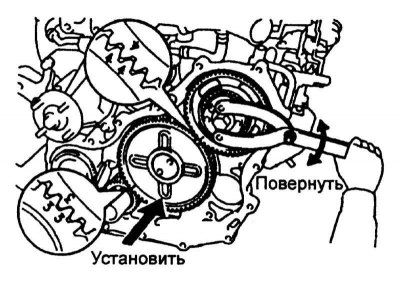
2. To install the intermediate gear, turn the fuel injection pump drive gear so that the "3" mark on the crankshaft gear aligns with the "4" mark on the fuel injection pump drive gear. Then engage the gears (refer to the accompanying illustration).