
Removing
Cylinder Head Installation Components for EGR Models
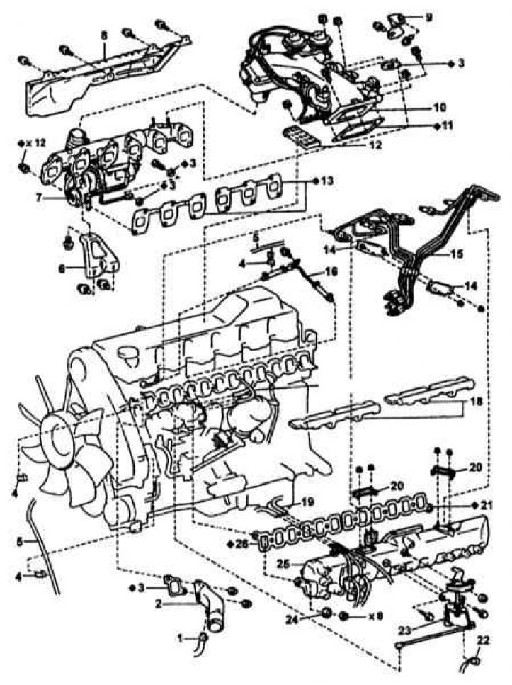
1 - Bypass water hose; 2 - Branch pipe; 3 - Gasket; 4 - Clamp; 5 - Vacuum hose; 6 - Turbocharger bracket; 7 - Turbocharger and exhaust manifold; 8 - Thermal protection screen; 9 - EGR valve bracket; 10 - Assembly of the inlet pipe; 11 - Gasket; 12 - Inlet pipe heat shield; 13 - Gasket; 14 - Clamp; 15 - High pressure fuel pipe; 16 - Fuel return pipe from nozzle No. 3; 17 - Vacuum hose; 18 - Thermal screen of the inlet pipeline; 19 - Vacuum hose; 20 - Clamp; 21 - Gasket; 22 - Connector for the gas pedal position sensor; 23 - Throttle actuator; 24 - Sealing washer; 25 - Inlet pipeline; 26 - Gasket
Cylinder Head Installation Components for Non-EGR Models
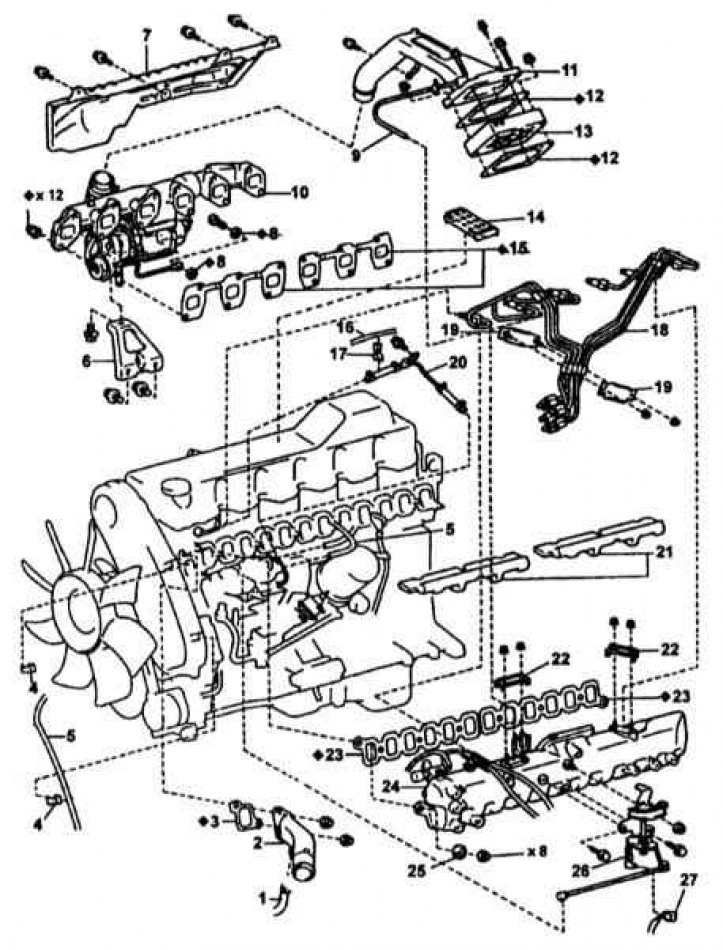
1 - Bypass water hose; 2 - Branch pipe; 3 - Gasket; 4 - Clamp; 5 - Vacuum hose; 6 - Turbocharger bracket; 7 - Thermal protection screen; 8 - Gasket; 9 - Vacuum hose; 10 - Assembling the turbocharger and exhaust manifold; 11 - Inlet pipe; 12 - Gasket; 13 - Inlet heater; 14 - Inlet pipe heat shield; 15 - Gasket; 16 - Vacuum hose; 17 - Clamp; 18 - High pressure fuel pipe; 19 - Clamp; 20 - Fuel return pipe from nozzle No. 3; 21 - Thermal screen of the inlet pipeline; 22 - Clamp; 23 - Gasket; 24 - Inlet pipeline; 25 - Sealing washer; 26 - Throttle actuator; 27 - Gas pedal position sensor connector (models with AT)
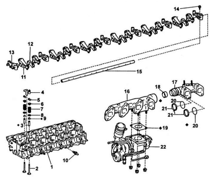
Camshaft Installation Components
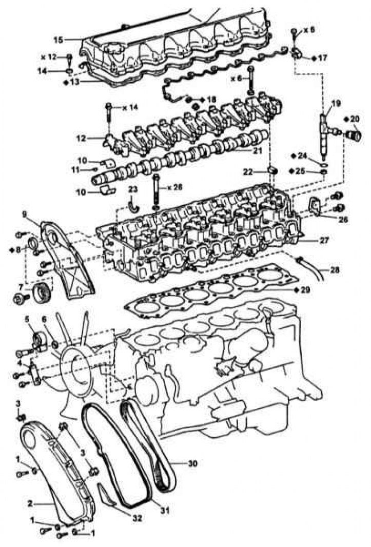
1 - Sealing washer; 2 - Timing belt cover; 3 - Coupler; 4 - Toothed belt tensioner; 5 - Tension roller; 6 - Washer; 7 - Pulley No. 1 of the camshaft; 8 - Camshaft seal; 9 - Camshaft oil seal housing; 10 - Camshaft bearing shells; 11 - Pulley key; 12 - Camshaft bearing cap; 13 - Gasket; 14 - O-ring; 15 - Cylinder head cover; 16 - Fuel return pipe from nozzle No. 1; 17.18 - Gasket; 19 - Nozzle; 20 - Seal of the nozzle holder; 21 - Camshaft; 22 - Segment plug; 23 - Thrust half ring; 24 - O-ring; 25 - Nozzle seat; 26 - Rear eye of the engine; 27 - Cylinder head; 28 - Bypass water hose (from injection pump); 29 - Cylinder head gasket; 30 - Toothed belt; 31 - Gasket; 32 - Insulator
1. The cylinder head installation components are shown in the illustrations above.
2. Drain coolant, remove air ducts and high pressure fuel pipes.
3. On models with EGR system:
- a. Disconnect three vacuum hoses from a vacuum tube on the inlet pipeline;
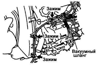
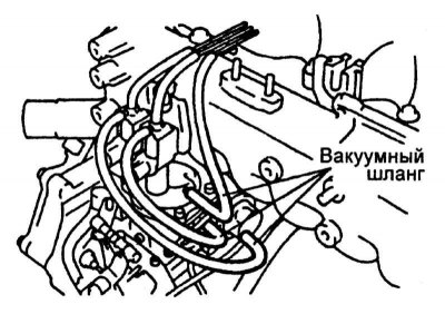
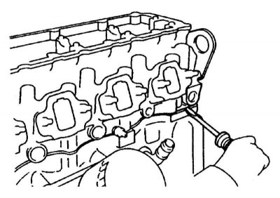
- b. Disconnect the vacuum hose from the three clips on the toothed belt cover, as well as the fuel return hose (refer to accompanying illustration);
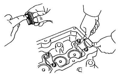
- c. Turn out two bolts and remove the EGR valve;
- d. Give two nuts of fastening of the EGR valve adapter to a final collector;
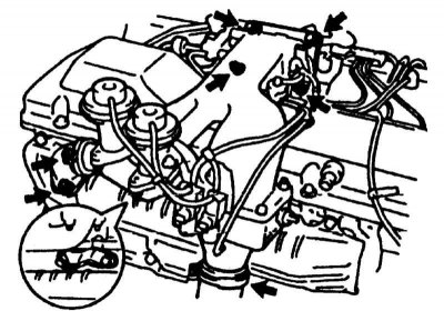
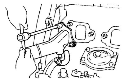
- e. Give two bolts and two nuts of fastening of a branch pipe of the inlet pipeline (refer to accompanying illustration);
- f. Disconnect the inlet pipe from the air hose and remove the pipe assembly with two gaskets and a screen.
4. On models without an EGR system:
- a. Remove the intake manifold and air heater;
- b. Disconnect a vacuum hose from a vacuum tube on the inlet pipeline;
- c. Turn out a bolt and disconnect the plug of weight from a head of cylinders;
- d. Give two nuts of fastening of the EGR valve adapter to a final collector;
- e. Give two bolts and two nuts of fastening of a branch pipe of the inlet pipeline;
- f. Disconnect the inlet pipe from the air hose and remove the pipe assembly with two gaskets and a screen.
5. Remove the high pressure fuel pipes.
6. On models with an EGR system, disconnect the three vacuum hoses from the injection pump (refer to accompanying illustration).
7. On models without an EGR system:
- a. Disconnect two vacuum hoses from high pressure fuel pump;
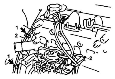
- b. Disconnect the vacuum hose from the two clips on the timing belt cover (refer to accompanying illustration);
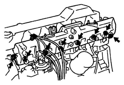
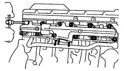
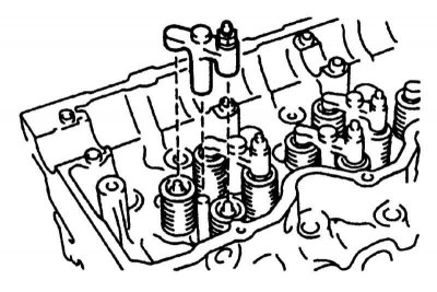
- c. Give 8 nuts, remove 8 washers, inlet pipeline and two gaskets (refer to accompanying illustration).
8. Remove the coolant outlet pipe (refer to accompanying illustration).
9. Remove nozzles.
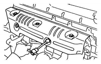
10. Give fasteners and remove the heat shield (refer to accompanying illustration).
11. Remove exhaust manifold with turbocharger (refer to accompanying illustration).
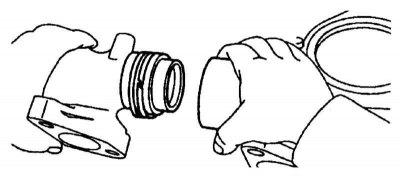
12a. Separate the parts of the exhaust manifold (refer to accompanying illustration).
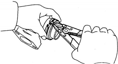
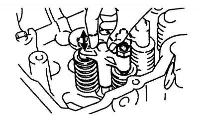
12b. Remove spring rings (refer to accompanying illustration).
13. Remove the cylinder head cover.
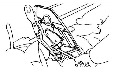
14. Turn out four bolts of fastening of a back cover of a belt to a head of cylinders and remove a cover (refer to accompanying illustration).
15. Remove the camshaft (see illustration at the beginning of the Section). For this:
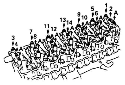
- a. Remove 7 bolts «A» (refer to accompanying illustration);
- b. Evenly loosen and remove the 14 remaining bolts in several passes and in the prescribed sequence;
- c. Remove the 7 bearing caps, 12 rocker arms, 6 injector hold-downs, rocker shaft assembly, and 7 upper bearing shells.
Note. Keep the removed parts complete with the rocker shaft, and the liners inserted into the bearing cover;
- d. Remove the camshaft, its thrust plate and 7 lower bearing shells.
Note. Arrange bearing shells and covers in the order of installation.
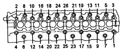
16. In several steps and in a set sequence (refer to accompanying illustration) turn out fixing bolts, remove a head of cylinders and lay it on wooden bars.
17. If the head cannot be removed, carefully pry it off with a screwdriver in the place indicated in the accompanying illustration.
Disassembly
The cylinder head assembly components are shown in the accompanying illustration.
Cylinder Head Assembly Components
1 - Cylinder head; 2 - Valve; 3 - Valve guide sleeve; 4 - Valve lever; 5 - Crackers; 6 - Upper spring plate; 7 - Valve spring; 8 - Lower spring plate; 9 - Oil scraper cap; 10 - ECT sensor; 11 - Rocker; 12 - Injector clamp; 13 - Camshaft bearing cap; 14 - Bolt of fastening of a cover of the bearing; 15 - Axis of rocker arms; 16 - Front of the exhaust manifold; 17 - The back of the exhaust manifold; 18 - Ring; 19 - Gasket; 20 - O-ring; 21 - Ring; 22 - Turbocharger
1. Take out pushers of valves and lay pushers in an installation order.
2. Remove the front and rear engine lifting eyes.
3. Remove the ECT sensor.
4. Remove the valve levers and arrange them in the order of installation (refer to accompanying illustration).
5. Remove valves. For this:
- A. Compress the spring with a puller and remove 2 crackers;
- b. Remove the spring plate, spring and its seat; arrange the parts of each kit in the order of installation;
- c. Remove oil seals.
Assembly
1. Thoroughly clean all parts and lubricate their friction surfaces with fresh engine oil.
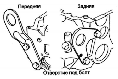
2. Install engine lifting eyes (refer to accompanying illustration).
3. Install the segment insert after applying sealant to it (refer to accompanying illustration).
4. Install the valve in the reverse order of removal.
5. Tap the end of the valve stem with a plastic mallet.
6. Install the valve lifters and shims. Make sure the pushers turn freely by hand.
7. Install the valve levers and make sure they move smoothly (refer to accompanying illustration).
8. Install the ECT sensor.
Installation
1. The mating surfaces of the cylinder heads and their covers must be absolutely clean and dry. Using a scraper, remove all traces of the old sealant and fragments of the destroyed gasket, then wipe the surfaces with a rag soaked in acetone. The presence of traces of oil on the mating surfaces can lead to the development of leaks.
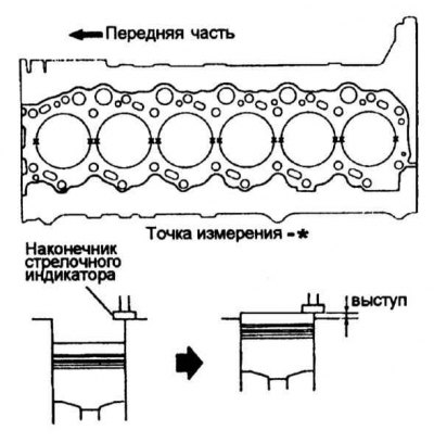
2a. Measure the maximum protrusion of each piston at two points, calculate the arithmetic mean of the protrusion and compare it with the requirements Specifications (refer to accompanying illustration).
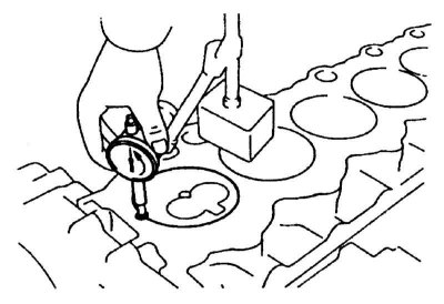
2b. If necessary, replace the piston assembly with the connecting rod (refer to accompanying illustration).
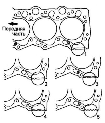
3. Determine the largest value of the protrusion of the piston and, in accordance with it, select the cylinder head gasket, guided by the table below.
Note. As spare parts, only gaskets No. 1, 3 and 5 are supplied with a thickness of 0.85–0.95, 0.95–1.05 and 1.05–1.15 mm, respectively.
The gasket number is determined by the number of cutouts on it (refer to accompanying illustration).
| Piston protrusion, mm | Gasket number |
| Not more than 0.225 | 1 |
| 0,226 – 0,325 | 3 |
| Not less than 0.326 | 5 |
4. Set the piston of the first cylinder to the TDC position.
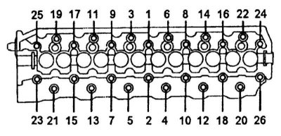
5. Place the cylinder head gasket on the cylinder block, lubricate the threads and bottom of the heads of the cylinder head bolts with engine oil and tighten the bolts by hand. Then tighten the bolts in the prescribed sequence with a force of 69 Nm, after which tighten them twice another 90 degrees, observing the sequence (refer to accompanying illustration).
Note. bolts «B» (№№ 21, 13, 5, 4, 12, 20) have a length of 133.5 mm, and the bolts «A» (rest) - 121.5 mm.
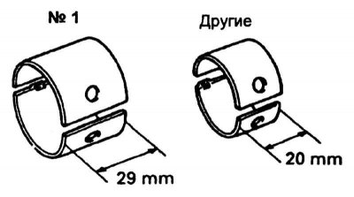
6a. Install 7 bottom bushings (refer to accompanying illustration).
Note. Install a bushing with a width in bearing #1, and bushings with a width of 20 mm in the remaining bearings.
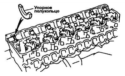
6b. Install the camshaft thrust ring (refer to accompanying illustration).
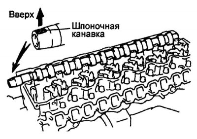
7. Lay the camshaft in the cylinder head with the keyway up (refer to accompanying illustration).
8. Install the top shells in the bearing caps.
9. Install bearing caps, rocker arms, injector clamps, and rocker shaft assembly.

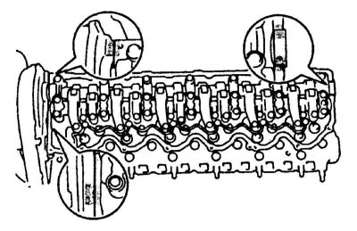
10. Tighten the 14 bearing cap bolts in sequence and the 7 bolts «A» (refer to accompanying illustration).
11. Install nozzles.
12. Check up and if necessary adjust valvate backlashes.
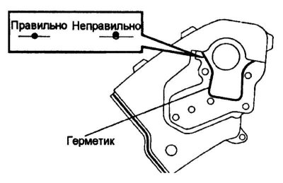
13. Remove the old sealant from the mating surface of the rear belt cover, apply new sealant and install the cover (refer to accompanying illustration).
14. Install pulleys and toothed belt.
15a. Insert the segmented rubber plugs into your slots, making sure they fit (refer to accompanying illustration).
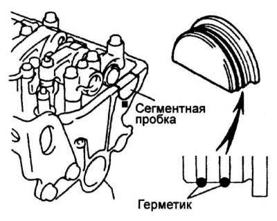
15b. Coat them with sealant (refer to accompanying illustration).
16. Lay the cylinder head cover gasket, install the cover itself with 12 new sealing washers and tighten its fastening bolts with a force of 6.5 Nm.
17. Install the engine rear bracket.
18. Assemble the exhaust manifold in the reverse order of its disassembly.
19. Install gaskets, turbocharger and exhaust manifold assembly.
20. Further installation is carried out in the reverse order to the dismantling of the components. Tighten fasteners to the required torque.