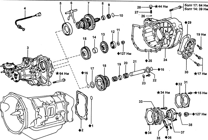
1 - O-ring, 2 - adapter gasket, 3 - front crankcase cover assembly, 4 - low gear switch (L4), 5 - front bearing holder, 6 - shift fork assembly, 7 - rear output shaft assembly, 8 - spacer, 9 - speedometer drive gear, 10 - washer, 11 - thrust washer, 12 - bearing, 13 - PTO drive gear, 14 - spacer, 15 - transfer case drive gear, 16 - O-ring, 17 - thrust washer, 18 - intermediate gear assembly, 19 - spacer, 20 - needle bearing, 21 - intermediate gear shaft, 22 - thrust washer, 23 - lock plate, 24 - crankcase, 25 - gasket, 26 - ball, 27 - spring, 28 - plug, 29 - gasket, 30 - side cover, 31 - rear cover, 32 - gasket, 33 - rear holder bearing, 34 - gasket, 35 - driven gear of the speedometer drive, 36 - ring gasket, 37 - connecting flange of the rear output shaft, 38 - washer.
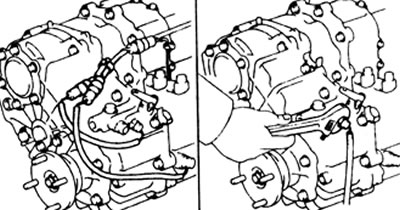
1. Disconnect the two sensor connectors on the transfer case.
2. Remove the low gear switch (L4).
3. Removing the driven gear of the speedometer drive.
A) Loosen the bolt on the rear bearing holder and remove the driven gear retainer plate.
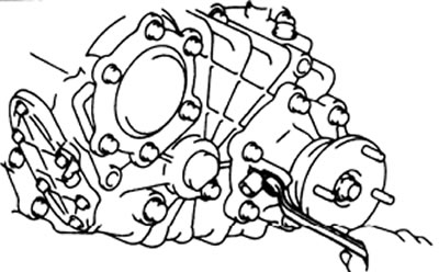
b) Remove the speedometer drive gear and remove the O-ring from it.
4. Remove six bolts and remove the side cover (for power take-off).
5. Using a feeler gauge, measure the clearance between the intermediate gear assembly and the thrust washer.
Permissible clearance - 0.275 - 0.625 mm
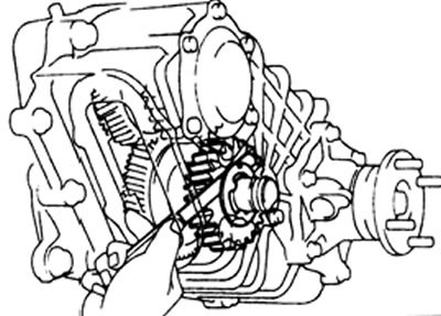
6. Turn away six bolts, then remove a back cover of a case and a lining.
7. Removing the gearbox output shaft locknut.
A) Using a hammer and chisel, loosen the caulked part of the locknut.
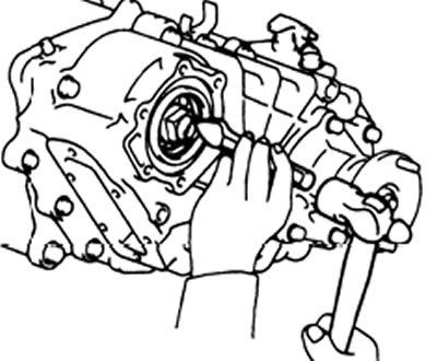
b) Move the external high-low shift lever on the crankcase to the position "H2" or "L4".
V) While holding the rear output shaft connecting flange with the special tool, loosen the lock nut and remove the washer.
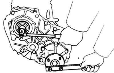
8. Removing the connecting flange of the rear output shaft.
A) Using a hammer and chisel, loosen the caulked part of the locknut.
b) While holding the flange with the special tool, remove the lock nut, then remove the washer and connecting flange.
9. Turn away six bolts and remove the holder of the back bearing together with a lining.
10. Remove the washer, speedometer drive gear and spacer from the rear output shaft.
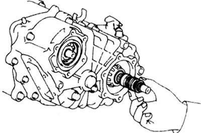
11. Turn away a bolt and remove a lock plate of a shaft of intermediate gear wheels.
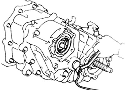
12. Turn away a stopper, then by means of a magnetic core take out a spring and a ball.
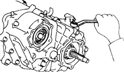
13. Removing the transfer case housing.
A) Remove fourteen bolts.
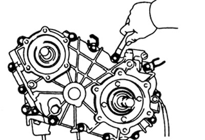
b) Tapping with a plastic hammer, disconnect the crankcase from the front cover.
V) Remove the crankcase gasket.
G) Remove the thrust washer from the intermediate gear shaft.
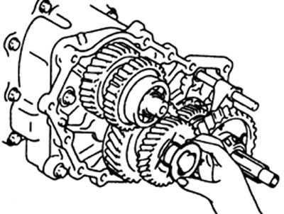
14. Remove the rear output shaft assembly with the high-low shift fork assembly.
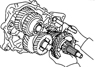
15. Removing the drive gear of the power take-off mechanism.
A) Using the special tool, remove the bearing from the gearbox output shaft.
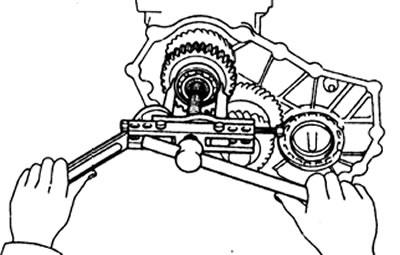
b) Remove the PTO drive gear, then remove the spacer.
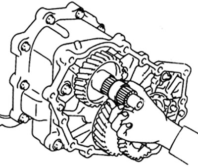
16. Using the special tool, remove the transfer case drive gear from the transmission output shaft.
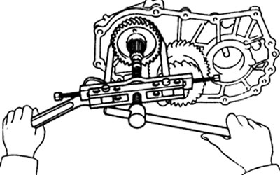
17. Removing the intermediate gear assembly.
A) Remove the O-ring from the intermediate gear shaft.
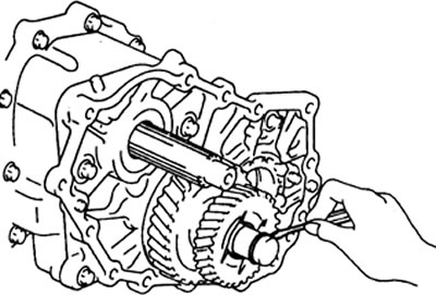
b) Remove the intermediate gear assembly with two bearings and spacer.
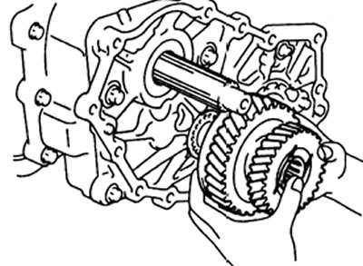
V) Remove the thrust washer from the intermediate gear shaft.
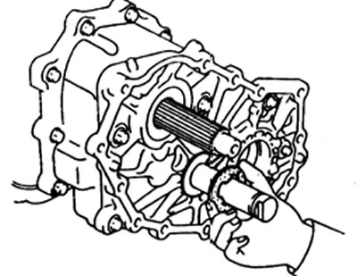
G) Remove the intermediate gear shaft.
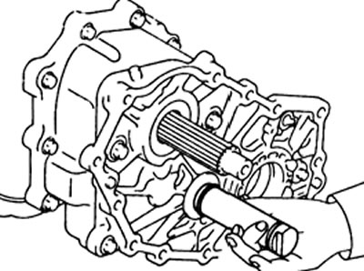
d) Remove the O-ring from the intermediate gear shaft.
18. Remove the rear output shaft front bearing retainer.
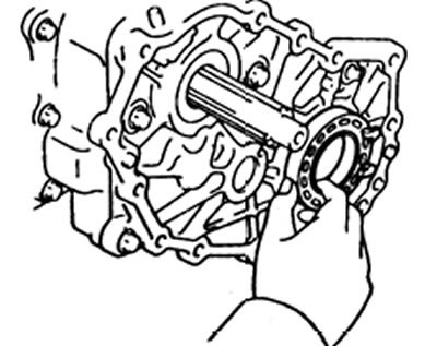
19. Remove the four bolts and, using a plastic hammer, disconnect the front crankcase cover from the transfer case adapter, then remove the gasket.
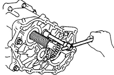
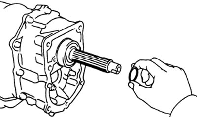
20. Remove the O-ring from the transmission output shaft.