
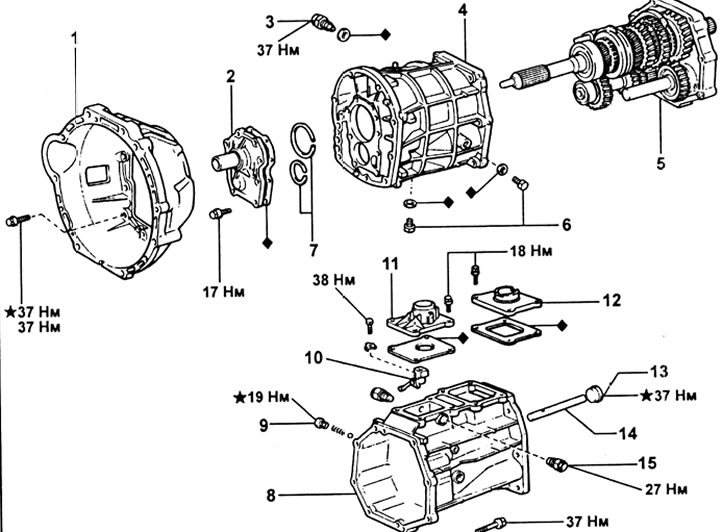
Gearbox G52.1 - clutch housing, 2 - input shaft bearing holder, 3 - reversing light switch, 4 - transmission housing, 5 - intermediate support, 6 - plug, 7 - circlip, 8 - transfer case adapter, 9 - plug, 10 - gear lever housing, 11 - gear lever cover, 12 - transfer case control lever cover, 13 - plug, 14 - gear lever shaft, 15 - stop pin.
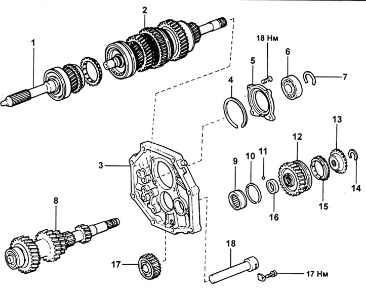
Gearbox G52 (continuation). 1 - input shaft, 2 - output shaft, 3 - intermediate support, 4 - circlip, 5 - rear output shaft bearing holder, 6 - bearing, 7 - circlip, 8 - intermediate shaft, 9 - bearing, 10 - circlip, 11 - ball, 12 - countershaft fifth gear, 13 - fifth gear synchronizer hub, 14 - retaining ring, 15 - synchronizer ring, 16 - spacer sleeve, 17 - reverse idler gear, 18 - reverse idler gear shaft move.
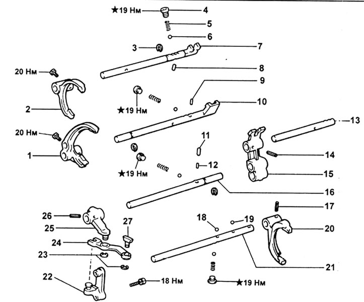
Gearbox G52 (continuation). 1 - shift fork No. 1, 2 - shift fork No. 2, 3 - retaining ring, 4 - plug, 5 - spring, 6 - ball, 7 - shift rod No. 2, 8 - locking pin No. 1.9 - locking pin No. 2, 10 - shift rod No. 1, 11 - locking pin No. 3,12 - locking pin No. 4, 13 - shift rod No. 5, 14 - pin, 15 - reverse gear engagement rod head, 16 - shift rod No. 3, 17 - pin, 18 - blocking ball, 19 - ball, 20 - shift fork No. 3, 21 - shift rod No. 4, 22 - bracket for reverse gear engagement, 23 - retaining rings, 24 - reverse gear engagement link, 25 - reverse gear engagement fork, 26 - pin, 27 - reverse gear engagement link finger.
1. Remove the clutch release fork and bearing.
2. Remove the transfer case.
3. Remove the switch of lanterns of a backing.
4. Turn away nine bolts of fastening and separate a case of coupling from a transmission.
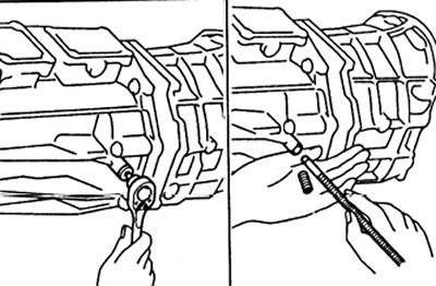
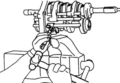
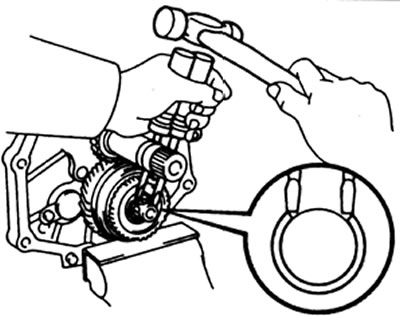
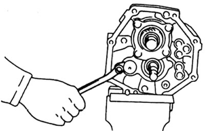
5. Removing the screw plug.
A) Using a socket wrench, remove the screw plug from the transfer case adapter.
b) Using a magnetic rod, remove the spring and ball.
6. Turn away four bolts and remove a cover of the lever of a gear change. Then remove the transfer case control lever cover.
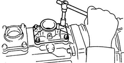
7. Remove the stop pins.
8. Removing the transfer box adapter.
A) Unscrew the plug from the transfer box adapter.
b) Loosen the gear lever housing mounting bolt.
V) Remove the shift lever housing and shaft.
G) Remove the eight bolts and use a plastic hammer to remove the transfer box adapter.
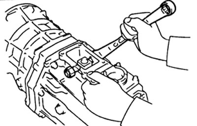
9. Turn away eight bolts, and remove the holder of the bearing of an input shaft and a lining.
10. Remove two lock rings of bearings of primary and intermediate shaft.
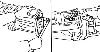
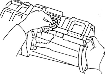
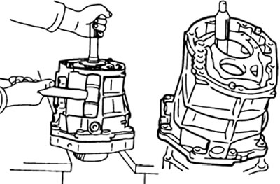
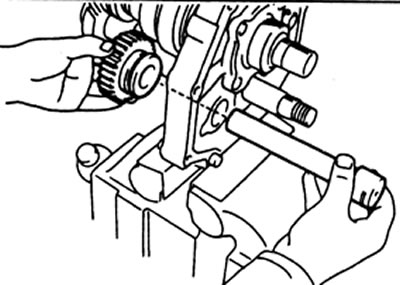
11. Removing the gearbox housing.
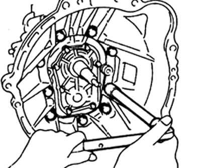
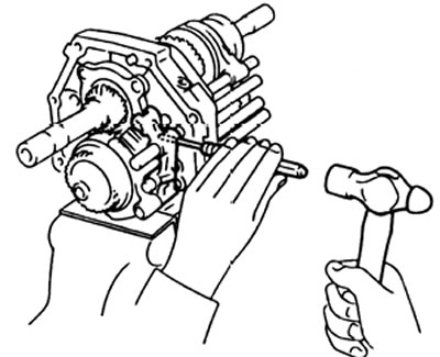
A) Position the gearbox as shown in the illustration.
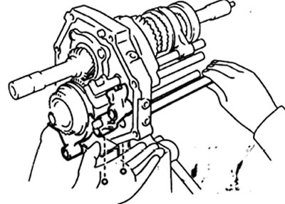
b) Using a plastic mallet, carefully pry the transmission housing from the intermediate support.
V) Remove the gearbox housing from the intermediate support as shown in the illustration.
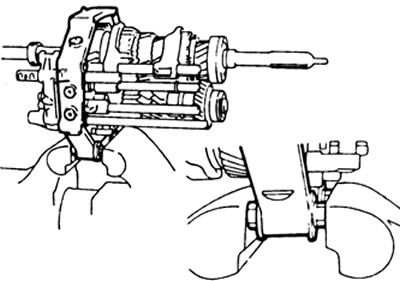
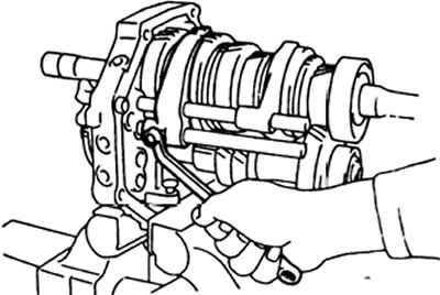
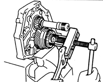
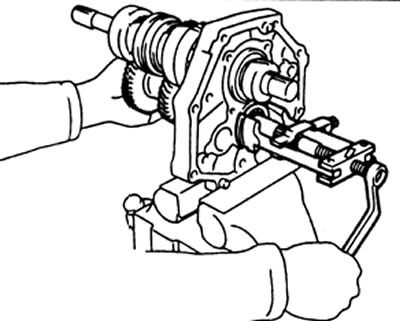
12. Install intermediate support in vise using two bolts, plate washers and nuts (see picture).
Attention: select and install such a number of plate washers that the threads of the bolts are not damaged.
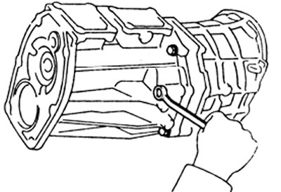
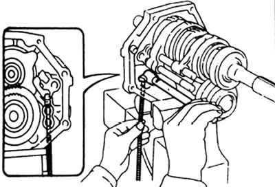
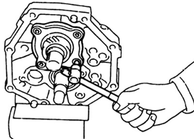
13. Removing the screw plugs.
A) Using an Allen wrench, remove the four plugs.
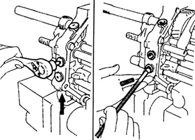
b) Using a magnetic rod, remove the springs and balls.
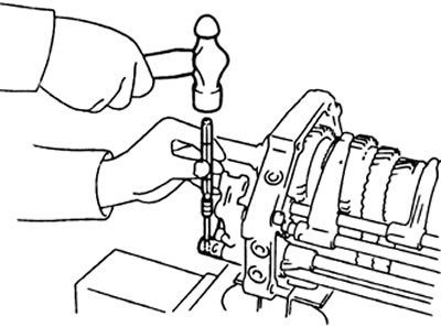
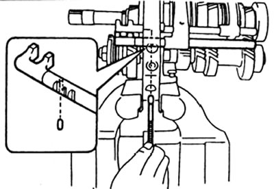
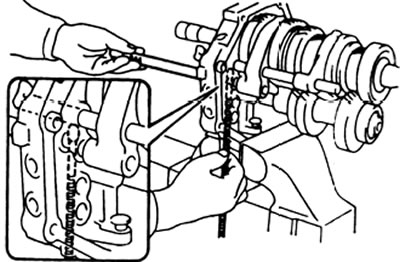
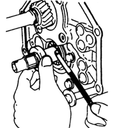
14. Using two screwdrivers and a hammer, remove the three circlips on the shift rods.
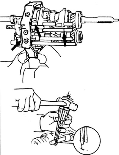
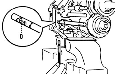
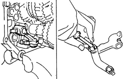
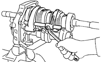
15. Using a punch and hammer, drive out the pin and remove the #5 shift rod.
16. Using a beard and hammer, knock out the pin from the shift fork #3.
17. Remove shift fork #3, shift shaft #4 and reverse gear shift rod head.
18. Removing the reverse gear engagement lever, the reverse gear engagement fork and the gearshift rod No. 3.
A) Using a magnetic rod, remove lock pin #4 from shift rod #3.
b) Using a punch and hammer, tap the pin out of the reverse gear fork.
V) Remove the #3 shift rod.
G) Remove lock pin #3 from intermediate support.
d) Remove the backstage assembly with the reverse gear fork.
e) Using a screwdriver, remove the two circlips, and separate the yoke and pin from the reverse shift gate.
19. Removal of rods No. 1 and No. 2 gear shifting, forks No. 1 and No. 2 gear shifting.
A) Using a magnetic rod, remove lock pin #2 from shift rod #2.
b) Turn away a fixing bolt of a fork No. 1 of a gear change.
V) Remove shift rod #1.
G) Remove lock pin #1 from intermediate support.
d) Turn away a fixing bolt of a fork No. 2 of a gear change.
e) Remove shift forks #1 and #2 and shift rod #2.
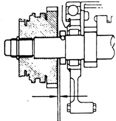
20. Using a feeler gauge, measure the axial clearance of the fifth gear countershaft gear.
Nominal clearance - 0.10 - 0.30 mm
Maximum clearance - 0.30 mm
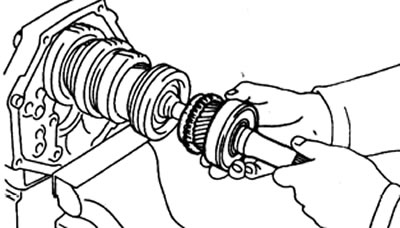
21. Removal of the fifth gear synchronizer hub, synchronizer ring, needle bearings and countershaft fifth gear.
A) Using two screwdrivers and a hammer, remove the circlip.
b) Using the special tool, remove the 5th gear synchronizer hub.
V) Remove the synchronizer ring, needle bearing and countershaft 5th gear.
22. Remove the spacer from the intermediate shaft, then use the magnetic rod to remove the ball.
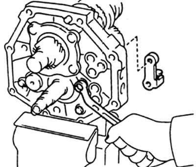
23. Turn away two bolts of fastening and remove an arm of a stage of inclusion of transfer of a backing.
24. Removing the reverse gear and shaft.
A) Loosen the bolt securing the reverse gear shaft stopper and remove the stopper.
b) Remove the reverse gear and shaft.
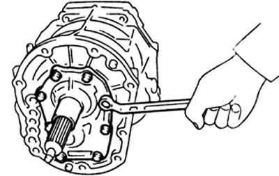
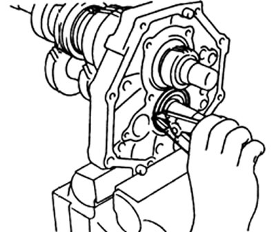
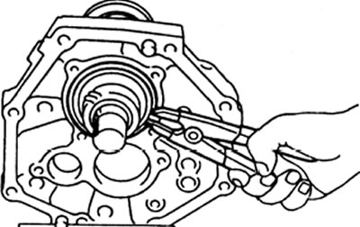
25. Using a socket wrench for a bolt with an internal hexagon, unscrew the four bolts and remove the holder for the rear bearing of the secondary shaft.
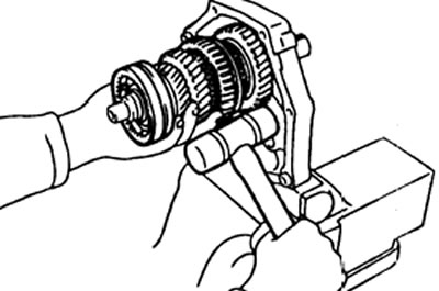
26. Removing the intermediate shaft.
A) Remove the intermediate shaft rear bearing circlip.
b) With special tool and tool head (12 mm), remove the intermediate shaft rear bearing.
V) Remove intermediate shaft.
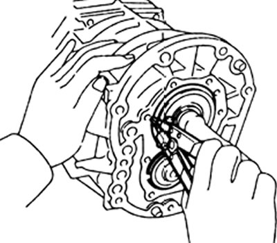
27. Separate the input shaft along with 13 bearing rollers and the synchronizer ring from the output shaft.
28. Remove the output shaft.
A) Remove the circlip from the main shaft center bearing.
b) Separate the output shaft from the intermediate support by pulling the output shaft towards you and gently tapping the intermediate support with a plastic mallet.
29. Checking the reversing light switch.
A) Check for continuity between the terminals when the switch is pressed (included).
b) Check for continuity between the terminals when the switch is not pressed (switched off).
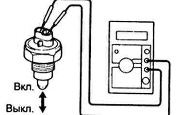
V) If the test result does not meet the specified conditions, then replace the switch.