
Note: checking and adjusting the thermal clearances in the valves is carried out on a cold engine.
1. Disconnect the accelerator cable with bracket.
2. Disconnect the wiring harness.
3. Disconnect the vacuum tubes.
4. Disconnect the crankcase ventilation hoses.
5. Remove the vacuum pump head cover.
A) Remove the cover cap No. 2 of the timing belt.
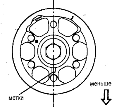
b) Turn the crankshaft clockwise until the mark on the camshaft pulley is at the bottom.
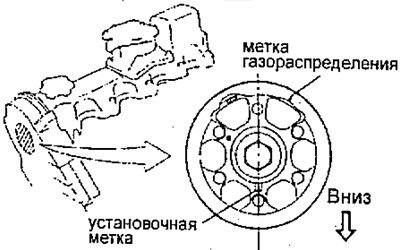
In this position, the vacuum pump piston is at BDC and the spring compression becomes the smallest.
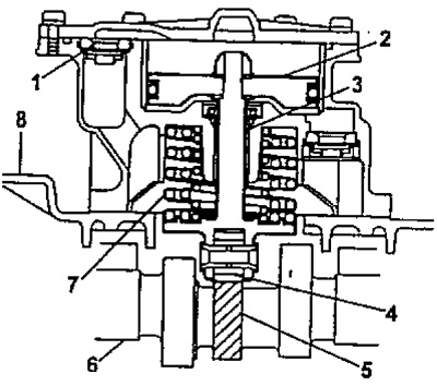
1 - safety valve,
2 - piston,
3 - stock,
4 - bearing,
5 - vacuum pump cam,
6 - camshaft,
7 - spring,
8 - block head cover.
V) Unscrew the two bolts of the cover No. 2 of the timing belt.
G) Disconnect the wire harness clamp.
d) Unscrew 10 bolts and remove the cover with the pump.
6. Set the piston of cylinder No. 1 to TDC of the compression stroke.
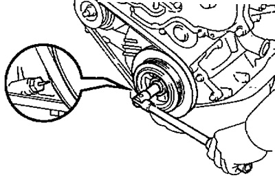
A) Turn the crankshaft pulley clockwise until its groove is aligned with the injection advance indicator.
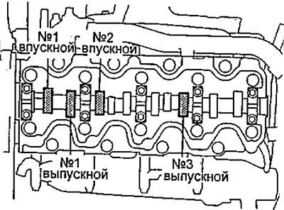
b) Check that the valve lifters for cylinder #1 are loose and the valve lifters for cylinder #4 are tight. If not, turn the crankshaft one turn (360°) and align the match marks as described above.
7. Check up a backlash in valves.
A) Check the clearances in the valves shown in the figure.
Using a feeler gauge, measure the clearance between the valve lifter and camshaft.
Write down the measurement results. These will later be used to determine the required thickness of the new shim.
valve clearances (measured on a cold engine):
- intake valve - 0.20-0.30 mm
- exhaust valve - 0.25-0.35mm
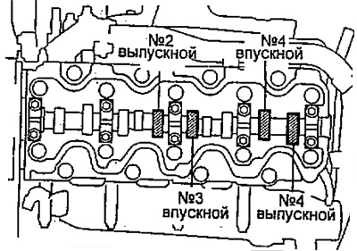
b) Rotate the crankshaft pulley one turn (360°) until its groove is aligned with the injection advance angle indicator.
V) Check the clearances in the valves shown in the figure.
8. Adjust valve clearances.
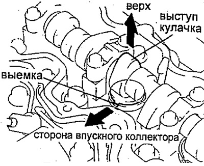
A) Remove the adjusting washer.
Rotate the crankshaft so that the camshaft lobe is pointing up.
Position the notch in the valve lifter so that it faces the intake manifold.
b) Using a special tool (A), press down on the valve lifter and install the special tool (IN) between the camshaft and valve lifter.
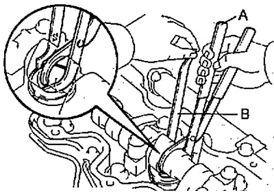
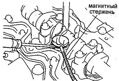
V) Using a small screwdriver and a magnetic bar, remove the old shim.
G) Measure the thickness of the removed shim with a micrometer. Calculate the thickness of the new shim so that the calculated gap satisfies the values given in the specifications:
- T - thickness of the removed washer, mm
- A - measured gap, mm
- N is the thickness of the new washer, mm
- Inlet valve - N \u003d T + [A- 0.25 mm]
- Exhaust valve - N \u003d T + [A- 0.30 mm]
Pick up an adjusting washer with a thickness closest to the calculated one.
Note: Shims come in 25 sizes, from 2.20mm to 3.40mm in 0.05mm increments. The thickness is indicated on the washer.
d) Install a new shim in the valve lifter.
e) Using a special tool (A), push down on the valve tappet and remove the tool (IN).
Check the valve clearance again.
9. Establish a cover of a head of the block of cylinders in gathering with the vacuum pump.
A) Install the camshaft pulley with the mark down.
b) Remove any remaining old sealant.
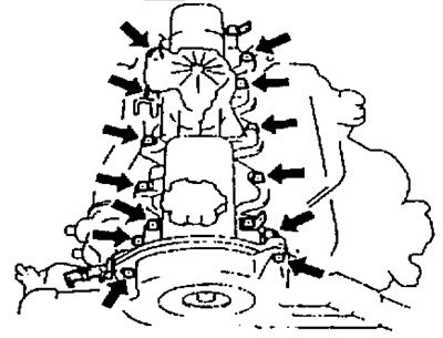
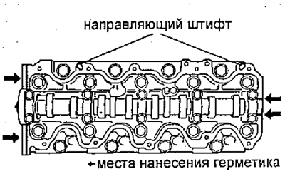
V) Apply sealant to the cylinder head at the locations shown in the illustration.
G) Install the head cover with ten bolts.
- Tightening torque - 14 Nm
d) Install the wire harness clamp.
e) Install and tighten the two #2 timing belt cover bolts.
- Tightening torque - 8 Nm
11. Connect the crankcase ventilation hose.
12. Connect the vacuum tubes.
- Tightening torque - 8 Nm
13. Connect the wiring harness.
14. Connect the accelerator cable.