



Contents: General information ↓ Maintenance recommendation ↓ Evaporator ↓ Heater radiator ↓ Capacitor ↓ Additional cooling circuit ↓ Maintenance recommendation ↓ Compressor ↓ Maintenance recommendation ↓
General information
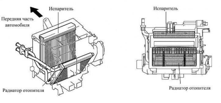
Fig. 1.95. Air conditioner design
The air conditioner is located almost in the middle of the dashboard, the evaporator and the heater radiator are installed along the longitudinal axis of the car. As a result, the air conditioner was made compact and light (Fig. 1.95).
The fan unit has a cabin ventilation system filter installed (high performance particulate arrester), excellent at removing dust and pollen from incoming air. The filter, designed to clean the air in the cabin, is made of polyester plastic. It is a flammable material and therefore easy to dispose of, which is an advantage from an environmental perspective.
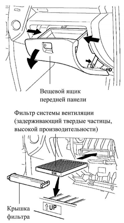
Fig. 1.96. Air conditioning system filters
The ventilation system filter is easy to replace, which simplifies maintenance. To do this, simply remove the glove compartment on the front panel (Fig. 1.96).
Maintenance recommendation
Under normal operating conditions, the filter should be replaced every 22,500 km, reducing this value to 15,000 when operating in dusty conditions. However, these values may vary depending on operating conditions and environmental conditions.
Evaporator
The evaporator is of the rotary flat design (RS). The evaporator consists of a tube, internal fins and a plate. The internal fins are made of thinner material, the evaporator is made more compact by reducing the height of the fins, the height of the fin tubes and the pitch of the fins. As a result, the evaporator has become much more compact and lighter.
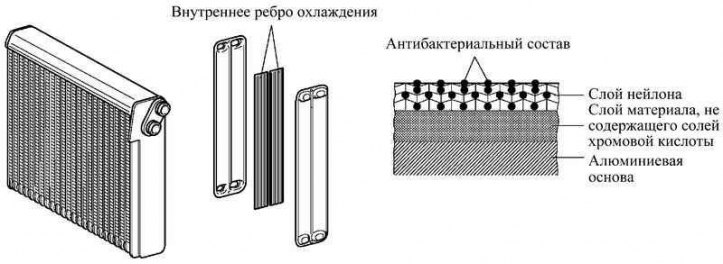
Fig. 1.97. Evaporator design
The evaporator surface is coated with a polymer coating with an antibacterial composition, which eliminates unpleasant odors and prevents the growth of bacteria. Under this coating there is a layer of material that does not contain chromic acid salts, which helps protect the environment (Fig. 1.97).
Heater radiator
The system uses a compact, lightweight and highly efficient straight-through (full flow) aluminum heater radiator.
The new Corolla Verso uses two types of heater cores (with or without positive temperature coefficient "PTC" heating elements).
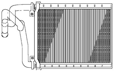
Fig. 1.98. Heater radiator
Two positive temperature coefficient "PTC" heating elements can be built into the heater radiator. PTCs are built into the heater radiator tubes. The PTCs have electrodes through which electric current is supplied to the positive temperature coefficient element. When current is passed through, the element heats the air passing through the fins (Fig. 1.98).
Capacitor
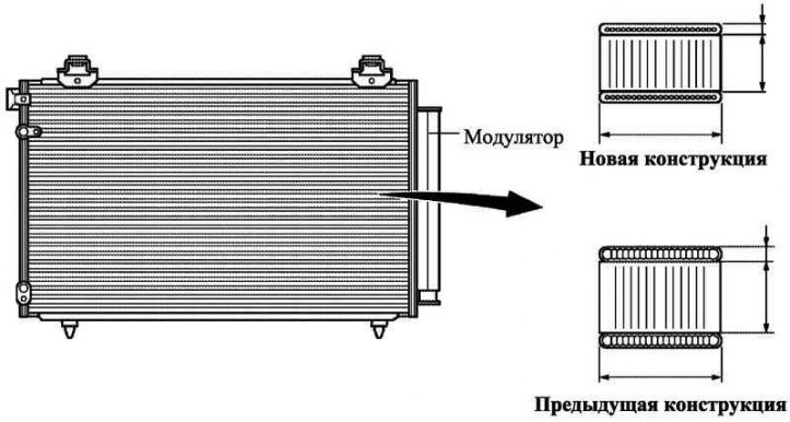
Fig. 1.99. Capacitor
The new Corolla Verso uses a condenser with an auxiliary cooler. This multi-pass condenser consists of two cooling sections: a condensing section and an auxiliary cooling section, as well as a gas-liquid separator (modulator), made as a single structure. To increase the efficiency of heat exchange in the condenser cooling system, an additional cooling cycle was introduced (Fig. 1.99).
The condenser on models with a hot gas heater consists of a condensing section, a solenoid valve, a connecting fitting and an accumulator. The condensing section is the same as on models without a hot gas heater.
The electromagnetic valve switches the refrigerant circulation circuits in accordance with signals coming from the control unit or the air conditioner ECU.
In the connecting fitting, the pressure of the refrigerant decreases and it partially turns into a gaseous state.
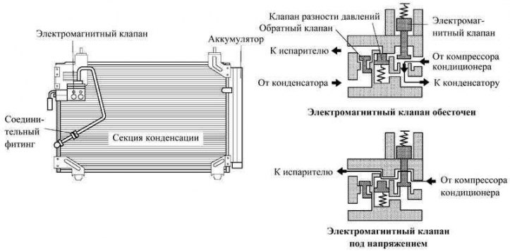
Fig. 1.100. Operating principle of a capacitor
The accumulator ensures the circulation of the refrigerant in the circuit in case of high temperature (or pressure) refrigerant at the compressor outlet. In case of low temperature or pressure, excess refrigerant is temporarily forced into the accumulator, thereby equalizing the flow rate (fig. 1.100).
Additional cooling circuit
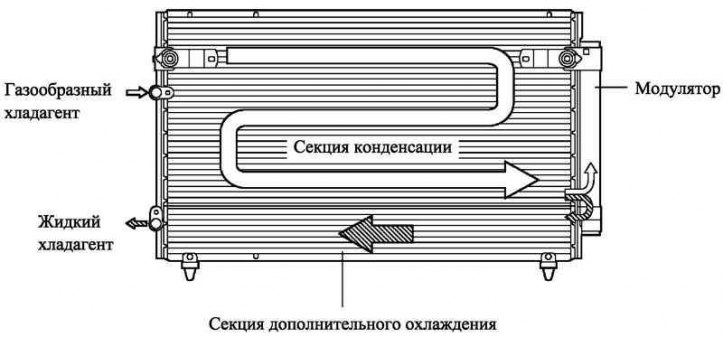
Fig. 1.101. Additional cooling circuit
After the refrigerant passes through the condensing section of the condenser, both the liquid refrigerant and the gaseous refrigerant that has not been converted into a liquid state are cooled again in the additional cooling section. Thus, the refrigerant that enters the evaporator is almost completely converted into a liquid state (fig. 1.101).
Maintenance recommendation
Due to the lack of a control window by which the state of the refrigerant could be determined, it is impossible to check the refrigerant level. The only way to check on the car is to measure the refrigerant pressure with a pressure gauge.
Compressor
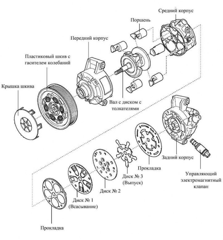
Fig. 1.102. Air conditioning compressor components
A compressor with continuously variable performance is used, the performance changes depending on the cooling power consumed by the air conditioner (fig. 1.102).
There is a solenoid valve that regulates the suction pressure.
The compressor pulley with torsional vibration damper is made of plastic.
Maintenance recommendation
The compressor cannot be disassembled and must therefore be replaced as an assembly.
(The article is taken from a web resource ToyotaMan.ru)