Disconnect the negative terminal from the battery terminal.
Set the #1 cylinder piston to TDC on the compression stroke.
Remove the timing chain cover plate.
Remove the timing belt drive.
Remove the #2 timing belt drive roller.
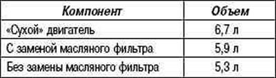
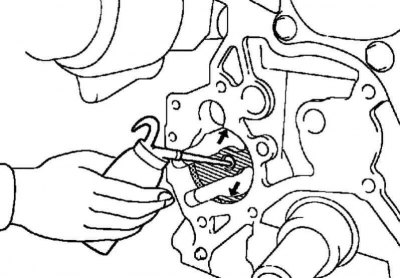
Removing the timing gear from the crankshaft
Pic. 2.448. Removing the timing gear from the crankshaft
If the timing gear cannot be removed from the crankshaft by hand, use the special tool SST (pic. 2.448).
Remove the front of the exhaust pipe.
Remove the #2 turbocharger heat shield.
Remove the #1 turbocharger heat shield.
Remove manifold bracket #2.
Remove the manifold bracket.
Remove the catalytic converter built into the exhaust manifold.
Remove the generator assembly.
Remove the #1 timing belt drive roller.
Remove the V-ribbed belt tensioner assembly.
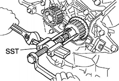
Removing the dipstick tube
Pic. 2.449. Bolt of fastening of a tube of an oil dipstick
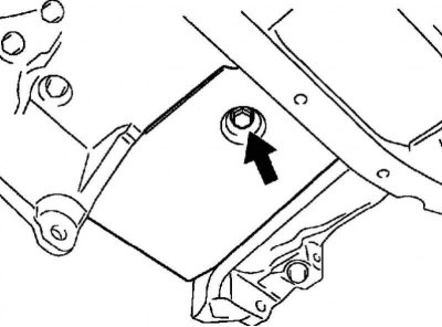
Remove the bolt securing the oil dipstick tube to the cylinder block (pic. 2.449).
Remove the oil dipstick tube along with the dipstick from the oil pan #1.
Remove the O-ring from the dipstick tube.
Removing the engine oil level sensor
Pic. 2.450. Bolts of fastening of the gauge of level of engine oil
Remove 4 bolts and remove the engine oil level sensor (pic. 2.450).
Note. Be careful not to drop the engine oil level sensor.
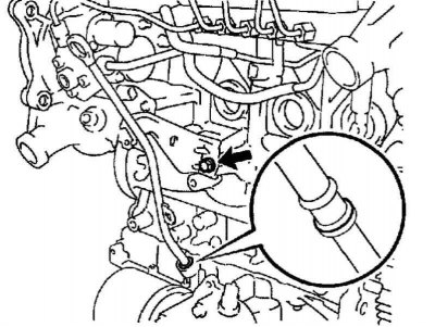
Removing the oil pan #2
Pic. 2.451. Fastening of the oil pan No. 2
Turn out 16 bolts and turn off 3 nuts of fastening (pic. 2.451).
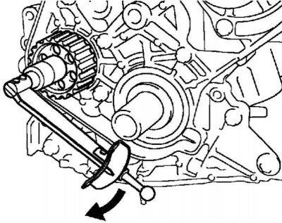
Pic. 2.452. Removing the oil pan No. 2
Insert blade of SST special tool between oil pan #1 and oil pan #2, cut off sealant and remove oil pan #2 (pic. 2.452).
Note. Be careful not to damage the #1 and #2 oil pan flanges.
Removing the mesh oil filter
Pic. 2.453. Mesh oil filter
Remove 2 bolts and 2 nuts and remove the oil strainer and gasket (pic. 2.453).
Removing the heat and sound insulating screen of the oil pan
Pic. 2.454. Bolt for fastening the heat and sound insulating screen of the oil pan
Remove the bolt and remove the heat and noise shield from the oil pan (pic. 2.454).
Removing the oil pan
Pic. 2.455. Pan mounting
Remove 19 bolts and 3 nuts (pic. 2.455).
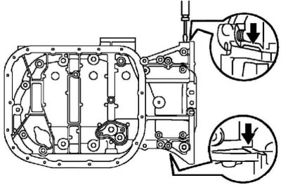
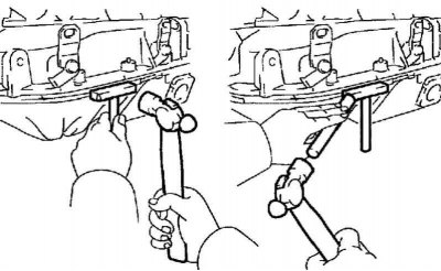
Pic. 2.456. The scheme of removal of the oil pan
By inserting a screwdriver between the oil pan #1 and the cylinder block, separate the oil pan (pic. 2.456).
Note. Be careful not to damage the cylinder block and #1 oil pan joint surfaces.
Remove the crankshaft position sensor.
Removing the oil pump assembly
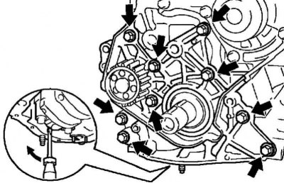
Pic. 2.457. Oil pump mounting bolts
Remove 9 mounting bolts (pic. 2.457).
Using a screwdriver between the oil pump and the main bearing cap, separate the oil pump.
Remove the gasket.
Installing the crankshaft oil seal
Lubricate the lip of the new oil seal with a light coat of multipurpose grease.
Note. The sealing lip must be free of sand, dirt and other foreign particles.
Using an SST tool and a hammer, drive in the new oil seal until its surface is flush with the oil pump surface.
Installing the oil pump assembly
Remove any remaining old FIPG sealant.
Be careful not to get oil on the seating surface of the oil pump and cylinder block.
Use a razor blade and scraper to remove sealant residue from the sealing surface.
Thoroughly clean all components and parts from small particles of sealant.
Wipe the sealing surfaces with solvent.
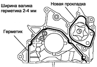
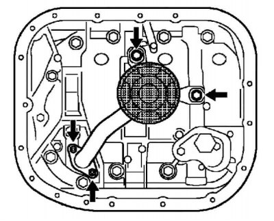
Pic. 2.458. Sealant application scheme
Apply sealant to the oil pump, as shown in Figure 2.458.
Note. Do not apply excessive amounts of sealant to the surface to be sealed.
Cut off the tip of the sealant package so that the hole diameter is 2-4 mm.
After applying the sealant, install the parts within 3 minutes and fix within 15 minutes. Otherwise, the cured sealant should be removed and then a fresh coat of sealant applied.
Immediately remove the tip from the tube, then close the tube with a cap.
Install a new gasket to the oil pump.
Pic. 2.459. Filling engine oil into the sleeve in the cylinder block
Fill 0.5cm3 or more engine oil into the sleeve in the cylinder block (pic. 2.459).
Lubricate the seating surfaces of the cylinder block and oil pump rotor with engine oil.
Fix the oil pump with 9 bolts.
Tightening torque: 31 Nm.
Pic. 2.460. Measuring the moment of resistance to rotation of the oil pump
Measure the torque of the oil pump (pic. 2.460).
Check that the pump rotates without binding or abnormal sounds.
Using a torque wrench, measure the moment of resistance to rotation of the pump.
Torque of resistance to rotation: 3.0 Nm.
Install the crankshaft position sensor.
Installing the oil pan
Remove any remaining old FIPG sealant.
Be careful not to get oil on the seating surface of the #1 oil pan, cylinder block, oil pump, and rear oil seal cover.
Using a razor blade and a scraper, remove sealant residue from sealing surfaces.
Thoroughly clean all components and parts from small particles of sealant.
Wipe the sealing surface with a volatile solvent.
Pic. 2.461. Sealant application scheme
Apply FIPG sealant to the flange of the oil pan No. 1, as shown in Figure 2.461.
Cut off the tip of the sealant package so that the hole diameter is 4-7 mm.
After applying the sealant, install the parts within 3 min and fix within 15 min. Otherwise, the cured sealant should be removed and then a fresh coat of sealant applied.
Immediately remove the tip from the tube, then close the tube with a cap.
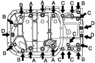
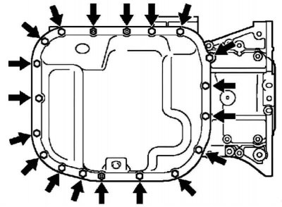
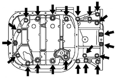
Pic. 2.462. Oil pan bolts
Secure the oil pan with 19 bolts and 3 nuts (pic. 2.462).
Torque:
- 42 Nm for bolt A;
- 21 Nm for bolt B;
- 11 Nm for bolt C;
- 12 Nm for nut D.
Installing the heat and sound insulating screen of the oil pan
Install the heat and noise shield of the oil pan and secure it with the bolt.
Tightening torque: 7.5 Nm.
Installing the strainer oil filter
Install a new gasket and secure the oil strainer with 2 bolts and 2 nuts.
Tightening torque: 21 Nm for bolt, 13 Nm for nut
Installing the oil pan #2
Remove any remaining old FIPG sealant.
Be careful not to get oil on the seating surface of the #1 and #2 oil pans.
Use a razor blade and scraper to remove sealant residue from the sealing surface.
Thoroughly clean all components and parts from small particles of sealant.
Wipe the sealing surfaces with solvent.
Note. Do not use normal solvent. It can damage painted surfaces.
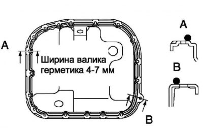
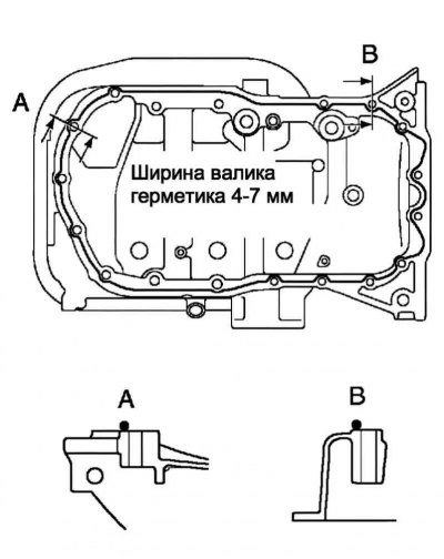
Pic. 2.463. Sealant application scheme
Apply sealant to the flange of the oil pan, as shown in Figure 2.463.
Cut off the tip of the sealant package so that the hole diameter is 4-7 mm.
After applying the sealant, install the parts within 3 min and fix within 15 min. Otherwise, the cured sealant should be removed and then a fresh coat of sealant applied.
Immediately remove the tip from the tube, then close the tube with a cap.
Secure the oil pan with 17 bolts and 2 nuts. Tighten the bolts and nuts evenly in several steps.
Tightening torque: 12 Nm.
Install the engine oil level sensor.
Tightening torque: 7.0 Nm.
Note. Install other components in the reverse order of removal.
Table 2.11. Filling volume of oil