
Note. Due to the significant weight of the tailgate assembly, it would be wise to enlist the help of an assistant.
Tailgate design
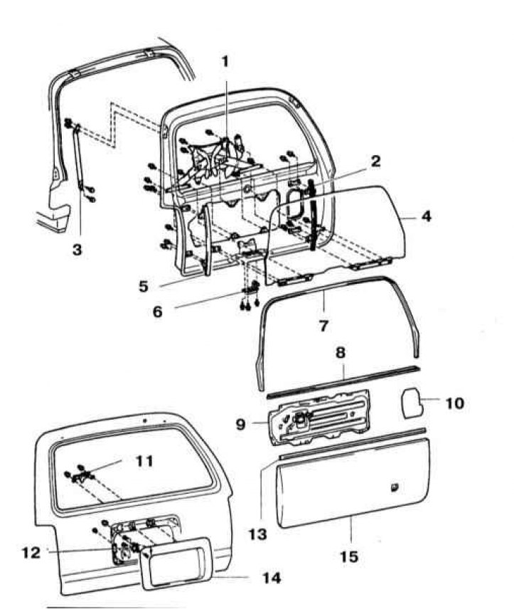
1 - Window regulator; 2 - Right window guide; 3 - Door stop; 4 - Rear glass; 5 - Left guide window; 6 - Door lock; 7 - Guide tape facing the window opening; 8 - External sealing tape; 9 - Service hole cover; 10 - Plate; 11 - Latch drive crank; 12 - Lock cylinder; 13 - Internal sealing tape; 14 - Facing panel of the license plate; 15 - Back door upholstery panel
1. Disconnect the negative cable from the battery.
Attention! If the stereo system installed in the car is equipped with a security code, before disconnecting the battery, make sure that you have the correct combination to activate the audio system!
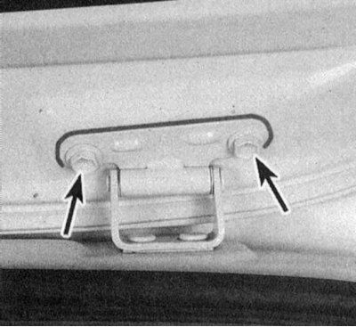
2. Open the tailgate and lock it securely in the raised position. Remove door stops (refer to illustration above).
3. Disconnect the wiring laid between the tailgate and the car body. To do this, release the bushing and disconnect the connectors.
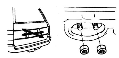
4. Circle the hinge strips with a marker and unscrew the bolts of their fastening (refer to accompanying illustration). With the help of an assistant, remove the tailgate assembly from the vehicle.
5. Installation is carried out in the reverse order.
6a. To replace the lock, it is necessary to remove the door inner trim panel, service window cover, window opening lining guide tape, facing, sealing tape, glass, power window regulator and guide chutes (see Section Removal and installation of glass and a regulator of a window regulator of a door of a back). Remove the door latch remote crank (refer to accompanying illustration).
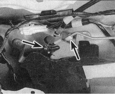
6b. Remove the drive mechanism. The facing panel of the license plate is attached to the tailgate of the car by means of a nut and five clamps, give the nut and, prying the panel, release the clamps. Give two fixing nuts and remove the cylinder of the lock assembly, if necessary, disconnecting the corresponding electrical wiring. Walk along the actuating rod and disconnect it, also disconnect the lock release cable (refer to accompanying illustration).
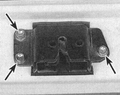
6c. Remove the three fixing screws (refer to accompanying illustration) and remove the door lock latch assembly. Installation is in the reverse order.
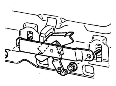
7a. The displacement of the door in the longitudinal direction is carried out by releasing the nuts that fasten the hinge strips to the car body (refer to accompanying illustration), then the loops are tapped with a hammer in the appropriate direction.
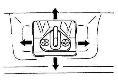
7b. Adjusting the position of the door in the body opening (right-left, up-down) produced by loosening the fasteners of the hinges on the door frame. The correct operation of the latch is achieved by adjusting the position of its striker (refer to accompanying illustration). After completing the adjustment, firmly tighten the appropriate fasteners.