
The electronic control system consists of sensors, an electronic control unit that includes one or more microprocessors, and actuators that directly affect engine systems.
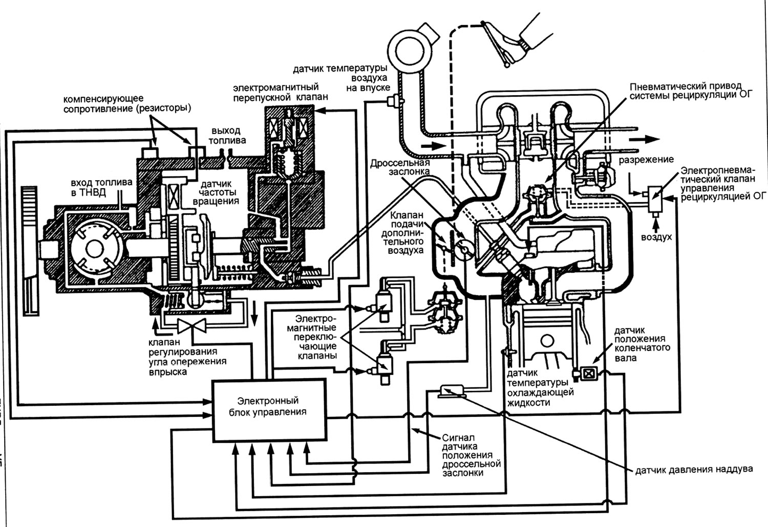
Information about the mode of operation and the state of the engine enters the control system from a variety of sensors. Sensors convert controlled (measurable) engine parameters into electrical signals, convenient for processing and transmission in the electronic control system. The signals from the sensors are fed to the inputs of the electronic control unit. The electronic unit, processing the received information according to the given algorithms, issues control signals to the actuators. The control algorithms implemented by the microprocessor of the electronic unit produce the optimal (the best) fuel consumption combination of fuel injection parameters (cyclic feed and injection advance angle) and air charge (boost pressure and degree of exhaust gas recirculation). The actuators that receive the control signals of the electronic unit are located respectively in the high pressure fuel pump (injection pump), in the intake manifold, between the intake and exhaust manifolds, in the turbocharger. Diagram of the electronic control system of a Toyota diesel engine with a high pressure fuel pump of the VE type is shown in Figure 2. A block diagram of the electronic control unit is shown in Figure. 1.
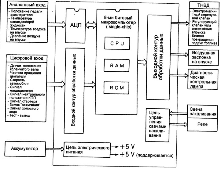
Pic. 1 Block diagram of the electronic control unit
Открыть большую картинку в новой вкладке »
Pic. 2 Scheme of the electronic control system of a Toyota diesel engine with high pressure fuel pump type VE