
2. If a malfunction is detected on the instrument panel, the control lamp lights up, and the electronic control unit enters the mode "drive home", sufficient to deliver the car to the repair shop.
3. Codes of malfunctions can be read out on signals of a control lamp.
Reading trouble codes
Normal test mode
1. Warm up the engine to operating temperature.
2. Turn off all optional equipment.
3. Turn on "ignition".
4. Place a jumper on the terminals TE1 and E1 of the diagnostic connector.
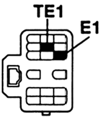
Diagnostic connector (type 1)
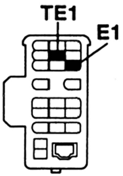
Diagnostic connector (type 2)
5. The fault code is determined by a series of flashes "tens-ones" control lamp.
6. For example, the lamp flashes 2 times, then pauses for 1.5 seconds, then flashes 4 times. This means code 24 (intake air temperature sensor).
7. If two or more fault codes are stored in the memory of the electronic unit, then the codes will be separated by a pause of 2.5 seconds.
8. If there are no malfunctions, the control lamp should flash at an interval of 0.25 seconds.
Test mode check
Note: The self-diagnostic system enables a more detailed check of the control system when the terminals TE2 and E1 of the diagnostic connector are bridged. This test mode for specialists and some of the fault codes listed in the table appear only in this test mode.
This test is more sensitive than a regular test.
It is possible to diagnose the starter and air conditioning signals.
1. Verification conditions
- the engine is warmed up to operating temperature;
- the battery is fully charged (voltage not lower than 11 V);
- throttle closed (throttle position sensor IDL contacts shorted);
- all additional equipment is switched off.
2. Turn off "ignition".
3. Put a jumper on the TE2 and E1 terminals of a diagnostic socket.
4. Turn on "ignition".
Note: lamp flashing «check the engine» confirms the inclusion of a test check.
5. Start the engine and drive faster than 5 km/h.
6. Create fault conditions (according to the owner).
7. After the test check, bridge the TE1 and E1 terminals of the diagnostic socket.
Note: "ignition" must be turned off when the terminals are bridged.
8. Read trouble codes.
9. Remove the jumpers from the diagnostic socket.
Note: the test check cannot be started if the jumper on terminals TE2 and E1 is installed when the "ignition".
If the requirements of paragraph 5 are not met, then codes 42 and 43 (starter and vehicle speed signals) will be memorized as a fault.
Normally, code 51 will appear when you turn on the air conditioner or take your foot off the accelerator pedal.
Fault code identification
| Code | Fault location |
| 12 | crankshaft position sensor |
| 13 | Engine speed sensor |
| 14 | Traction relay for changing the injection advance or fuel pressure |
| 16 | Automatic transmission signal to the electronic control unit |
| 17 | Electronic control unit signal |
| 22 | Engine coolant temperature sensor signal |
| 24 | Intake air temperature sensor |
| 32 | Injection pump resistor signal |
| 33 | Throttle signal |
| 35 | Boost pressure sensor signal |
| 39 | Fuel Temperature Sensor Signal |
| 41 | Throttle position sensor signal |
| 42 | Vehicle speed sensor signal |
| 43 | starter signal |
| 51 | A/C switch, neutral position switch or throttle position sensor signal |
| 99 | Engine start inhibit system (immobilizer) |
Erasing fault codes
1 Turn off "ignition".
2 Remove the ECU fuse or disconnect the battery for one minute or more at low temperatures.
Note: Removing the battery will erase the memory of other electronic devices, such as clock time.
3 Road test the vehicle.
4. Repeat the diagnostic procedure and make sure there are no trouble codes.